
|
|
Forum Index : Microcontroller and PC projects : Stepper Project
| Author | Message | ||||
| PhenixRising Guru Joined: 07/11/2023 Location: United KingdomPosts: 2003 |
Caution: How do you know when the axis has been physically bumped during power-down? |
||||
| PhenixRising Guru Joined: 07/11/2023 Location: United KingdomPosts: 2003 |
Not applicable with open-loop steppers but I keep my encoders/control-circuit alive with a UPS. CNC machines can have their main power cycled just to reset some other fault and it's a pain in the buttski to have to re-home.  |
||||
Bryan1 Guru Joined: 22/02/2006 Location: AustraliaPosts: 2155 |
Well time for the fun to start   Now the LCD pcb's should be here next week as they are in Melb and should be over in Adelaide by Monday Well first observations 1. Didn't put in mounting holes 2. The 5V regulator board has to go on the underside 3. With the RTC footprint the I2C breakout has to go on the underside Now after looking for the scotty diode I just have the Bat46 here which is a 150mA one so would that be enough for powering the pico 2 Regards Bryan Edited 2026-05-29 09:39 by Bryan1 |
||||
| Bryan1 Guru Joined: 22/02/2006 Location: AustraliaPosts: 2155 |
Well Guy's some good signs 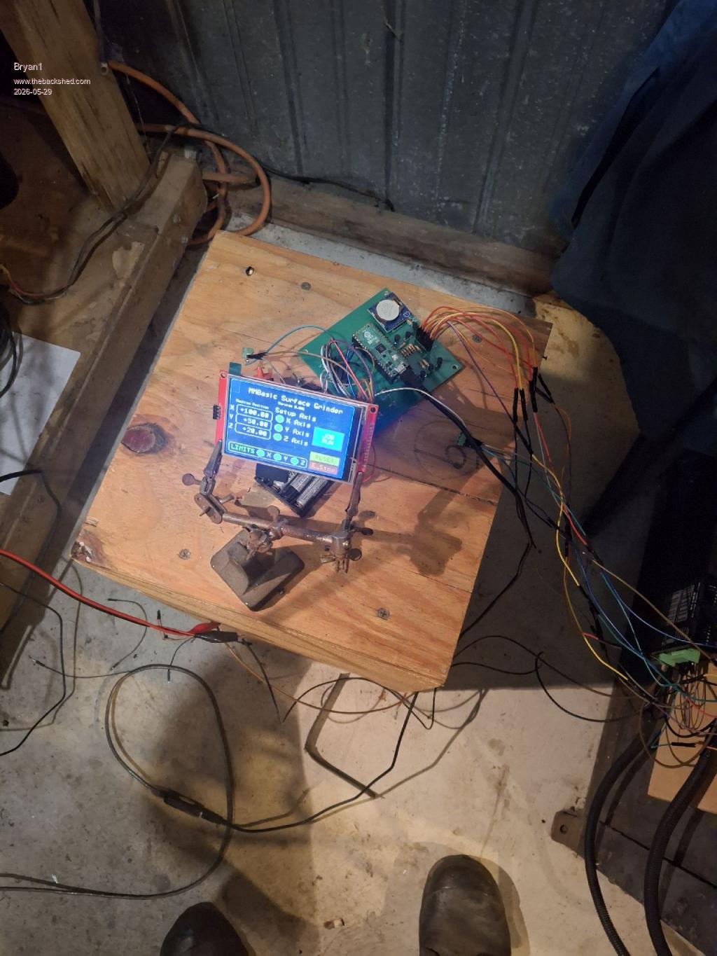 Now silly me just used Lyles LCD suggestions and I left out the second SPI pins as 2 of each are used. Easy fix got some old 2 pin connectors so gerry rigged up the SPI lines also with the 5 volt pullups on the DM556's I brought all 3 out and did the same with a 3 post connector for them. So after lunch time for testing this all out. Regards Bryan |
||||
| Bryan1 Guru Joined: 22/02/2006 Location: AustraliaPosts: 2155 |
Anyway for this PCB this is the options > option list PicoMite MMBasic RP2350A V6.03.00RC9 OPTION SYSTEM SPI GP18,GP19,GP16 OPTION SYSTEM I2C GP10,GP11 OPTION FLASH SIZE 4194304 OPTION COLOURCODE ON OPTION CPUSPEED (KHz) 200000 OPTION LCDPANEL CONSOLE OPTION DISPLAY 26, 60 OPTION LCDPANEL ST7796S, LANDSCAPE,GP15,GP14,GP13,GP20 OPTION GUI CONTROLS 75 OPTION TOUCH GP12,GP17 GUI CALIBRATE 0, 3951, 3900, -1289, -854 Now silly me had the X and Z axis the wrong way around now I started getting vertical lines across the screen and changing the backlight did get rid of it. I am running RC9 so I'm going to update to RC14 Now what I found as we pulled up the Enable when I start the program the enable is off and when I remove a connection the Enable is right so with the next pcb design I do think the enable should be pulled down. I found this interference with the LCD is getting worse so I'm going to wait until the LCD boards get here, anyway all 3 axis's are working nicely Also I did notice as the LCD is powered by the 5V input I turn the AAA's on first and with the console it does boot to the prompt. Now when I take the USB off the pico 2 the LCD goes bonkers just flashing really wide vertical bars. Now doing a reset does cure that problem Regards Bryan Edited 2026-05-29 16:29 by Bryan1 |
||||
| Bryan1 Guru Joined: 22/02/2006 Location: AustraliaPosts: 2155 |
Well I did manage to have another play and put a dial on the Z axis, now I put a grinding wheel on and found with the spring pressure with the wheel 5mm above the magnetic table the stepper can't handle it. Now go up 2mm and the stepper has no problem so did the 1mm movement up and down where under the spring pressure the drift is down to 0.03mm or a thou in the old school so I do think we can live with that. Not sure why these vertical white lines are happening as when I did the last test got close to 15 minutes before they came back and I did find putting the backlight on 5 did make it better. But when those lines do start no backlight adjustment works so a 10 minute reset is needed. |
||||
| Mixtel90 Guru Joined: 05/10/2019 Location: United KingdomPosts: 8964 |
Isn't it lovely moving from breadboard to PCB? :) Plenty of room for fixing holes, no worries. The 5V regulator may or may not need a heatsink, affecting where it can be fitted in most cases. A TO220 package can dissipate about 1W in free air so, coming from 12V, it will be dropping 7V. 1W dissipation would allow about 1/7 = 140mA without a heatsink, just keeping the tab clear of the PCB. A Pico usually draws rather less than 50mA, how much less depends on CPU speed. You can get it down to 10 or 12mA at very low speeds. The BAT46 won't notice if you don't tell it. :) Nice board. :) Mick Zilog Inside! nascom.info for Nascom & Gemini Preliminary MMBasic docs & my PCB designs |
||||
| Bryan1 Guru Joined: 22/02/2006 Location: AustraliaPosts: 2155 |
Mick these the Regulators I'm using and they are 600mA rated so it should be no problems powering the LCD and pico 2. Now with my LCDboard the extra SPI lines are all taken care of so when they get here I will be sending a couple over to Lyle to play with. Regards Bryan |
||||
| Mixtel90 Guru Joined: 05/10/2019 Location: United KingdomPosts: 8964 |
Ah, yes. The S09 converter. :) I've reverse engineered that and now have the resistor values for all the standard voltages and how to make it any sensible voltage or variable from 3V to 10.5V (although I've not tested that as I don't have a 250K LIN pot at the moment). I thought it would make a very cute and useful portable power supply. It's a pretty standard SEPIC buck/boost configuration with an active high enable pin. Input from 3V to 15V. Mick Zilog Inside! nascom.info for Nascom & Gemini Preliminary MMBasic docs & my PCB designs |
||||
| PhenixRising Guru Joined: 07/11/2023 Location: United KingdomPosts: 2003 |
Hi Mick, I forgot to ask the last time that you mentioned lower CPU speed: What about the 100KHz stepper "engine"? Affected or not? |
||||
| matherp Guru Joined: 11/12/2012 Location: United KingdomPosts: 11636 |
I'm running a single stepper with a cpu speed of 48MHz on a battery operated system. Haven't tried with more motors and more complex g-code Edited 2026-05-29 18:56 by matherp |
||||
| Mixtel90 Guru Joined: 05/10/2019 Location: United KingdomPosts: 8964 |
We tend to forget that 48MHz is still a pretty reasonable speed for a lot of things. Your processor simply spends less time in "waiting for something to happen" loops while using less power. We get a bit spoiled nowadays. lol Mick Zilog Inside! nascom.info for Nascom & Gemini Preliminary MMBasic docs & my PCB designs |
||||
| Bryan1 Guru Joined: 22/02/2006 Location: AustraliaPosts: 2155 |
Ok I finally went and asked Claude [CODE Option EXPLICIT Option DEFAULT NONE Option console serial Colour RGB(white), RGB(black) Const X_POSition = 1, xsetup = 2, Y_POSition = 7, ysetup = 3, zsetup = 4 Const Z_POSition = 5, Page_1 = 6, X_POSition1 = 8, Y_POSition1 = 9 Const Z_POSition1 = 10, XPOS = 11, toggleL = 12, toggleR = 13 Const YPOS = 16, XplusL = 17, XminusL = 18 Const YplusL = 19, X1 = 20, Y1 = 21, Z1 = 22, LS_Frame = 23, JOB_RUN = 24 Const ES_RESET = 25, ZPOSi = 28 Const PAGE_1TITLE = 29, Z0 = 30, Xcap = 31, ver = 32, X0 = 33 Const Y0 = 34, XPOSi = 35, YPOSi = 36, Ycap = 37, Lcap = 38 Const E_Stop = 39, escap = 40, Zcap = 41, ZPOS = 42, axis_show = 43 Const axis_adj = 44, XFPOS = 45, YFPOS = 46, ZFPOS = 47, XFtext = 48 Const YFtext = 49, ZFtext = 50 ' Run screen control constants (page 7) Const RUN_TITLE = 60 ' Caption "Grinding Cycle" Const RUN_START = 61 ' Start button Const RUN_PAUSE = 62 ' Pause button Const RUN_STOP = 63 ' Stop button Const RUN_ZSTEP = 64 ' Numberbox - Z step size override Const RUN_ZFEED = 65 ' Numberbox - Z feedrate override Const RUN_XCAP = 66 ' Caption X pos label Const RUN_YCAP = 67 ' Caption Y pos label Const RUN_ZCAP = 68 ' Caption Z pos label Const RUN_XPOS = 69 ' Displaybox X position Const RUN_YPOS = 70 ' Displaybox Y position Const RUN_ZPOS = 71 ' Displaybox Z position Const RUN_CYCAP = 72 ' Caption "Cycle Count" Const RUN_COUNT = 73 ' Displaybox cycle counter Const RUN_ZSCAP = 74 ' Caption "Z Step" Const RUN_ZFCAP = 75 ' Caption "Z Feed" Const RUN_STAT = 76 ' Caption status line Const RUN_ZSTEP_B = 77 ' Manual Z step button Const RUN_MAIN = 78 ' Back to main button Const RUN_ZDEP = 79 ' Numberbox total Z depth Dim integer R_Page, S.STAT Dim integer CycleState ' 0=idle 1=X fwd 2=X back 3=Y index 4=Z step 5=done Dim integer CycleCount ' Y pass counter Dim integer ZStepCount ' how many Z steps taken Dim integer CyclePaused ' 1=paused Dim float ZStartPos ' Z position when cycle started Dim float ZTotalDepth ' total Z depth to grind Dim float ZStepSize ' step size per Y pass Dim float ZStepFeed ' Z step feedrate Dim float XStartPos, XEndPos ' X reciprocating limits Dim float YStartPos, YEndPos ' Y traversing limits Dim integer XDir ' 1=forward, -1=back Dim N.POSX$, O.POSX$, N.POSY$, O.POSY$, N.POSZ$, O.POSZ$ On error skip Stepper close CLS SETUP_SCREEN SETUP_RUN_SCREEN Stepper init 0.05, 150, GP22 Stepper axis X, GP2, GP3, ,,, 450,, Stepper axis Y, GP4, GP5, ,,, 800,, Stepper axis Z, gp6, gp7, gp1,, 6380,, Stepper hwlimits gp26, gp27, gp28, gp26, gp27, gp28 Stepper spindle GP0 Stepper POSition X, 100 Stepper POSition Y, 50 Stepper POSition Z, 20 GUI interrupt TOUCHDOWN SetTick 200, Show_POS SetTick 100, RUN_CYCLE ' state machine poll GUI page 1, 6 Stepper RUN Do : Pause 100 : Loop Until Inkey$ <> "" Pause 250 Stepper close End ' --------------------------------------------------------------- Sub TOUCHDOWN ' --- Page navigation from main --- If Touch(ref) = JOB_RUN Then GUI page 7, 6 : R_Page = 4 EndIf If Touch(ref) = 20 Then GUI page 2, 5, 6 : R_Page = 1 : CtrlVal(52) = "42" : CtrlVal(53) = "53" EndIf If Touch(ref) = 21 Then GUI page 3, 5, 6 : R_Page = 2 : CtrlVal(52) = "60" : CtrlVal(53) = "71" EndIf If Touch(ref) = 22 Then GUI page 4, 5, 6 : R_Page = 3 : CtrlVal(52) = "80" : CtrlVal(53) = "91" EndIf If Touch(ref) = Page_1 Then GUI page 1, 6 : R_Page = 0 EndIf ' --- Run screen back to main (only if not running) --- If (Touch(ref) = RUN_MAIN) And (CycleState = 0) Then GUI page 1, 6 : R_Page = 0 EndIf ' --- Axis jog pages --- If (Touch(ref) = toggleL) And (Peek(stepper active) = 0) Then Select Case R_Page Case 1 : Stepper GCODE G1, X, Peek(stepper X) + CtrlVal(XPOS), f, CtrlVal(XFPOS) Case 2 : Stepper GCODE G1, Y, Peek(stepper Y) + CtrlVal(YPOS), f, CtrlVal(YFPOS) Case 3 : Stepper GCODE G1, Z, Peek(stepper Z) + CtrlVal(ZPOS), f, CtrlVal(ZFPOS) End Select EndIf If (Touch(ref) = toggleR) And (Peek(stepper active) = 0) Then Select Case R_Page Case 1 : Stepper GCODE G1, X, Peek(stepper X) - CtrlVal(XPOS), f, CtrlVal(XFPOS) Case 2 : Stepper GCODE G1, Y, Peek(stepper Y) - CtrlVal(YPOS), f, CtrlVal(YFPOS) Case 3 : Stepper GCODE G1, Z, Peek(stepper Z) - CtrlVal(ZPOS), f, CtrlVal(ZFPOS) End Select EndIf ' --- E-Stop / Reset --- If Touch(ref) = ES_RESET Then If S.Stat = 0 Then CycleState = 0 CyclePaused = 0 Stepper POSition x, 100 Stepper POSition y, 50 Stepper POSition z, 20 Stepper run CtrlVal(RUN_STAT) = "RESET" EndIf EndIf ' --- Run screen buttons --- If Touch(ref) = RUN_START Then If CycleState = 0 And Peek(stepper active) = 0 Then ' Capture start state ZStartPos = Peek(stepper Z) ZStepSize = CtrlVal(RUN_ZSTEP) ZStepFeed = CtrlVal(RUN_ZFEED) ZTotalDepth = CtrlVal(RUN_ZDEP) XStartPos = Peek(stepper X) XEndPos = Peek(stepper X) + CtrlVal(XPOS) YStartPos = Peek(stepper Y) YEndPos = Peek(stepper Y) + CtrlVal(YPOS) XDir = 1 CycleCount = 0 ZStepCount = 0 CyclePaused = 0 CycleState = 1 ' start X forward pass CtrlVal(RUN_COUNT) = "0" CtrlVal(RUN_STAT) = "RUNNING" GUI disable RUN_START GUI enable RUN_PAUSE GUI enable RUN_STOP EndIf EndIf If Touch(ref) = RUN_PAUSE Then If CycleState > 0 And CycleState < 5 Then If CyclePaused = 0 Then CyclePaused = 1 Stepper halt CtrlVal(RUN_STAT) = "PAUSED" Else CyclePaused = 0 Stepper run CtrlVal(RUN_STAT) = "RUNNING" EndIf EndIf EndIf If Touch(ref) = RUN_STOP Then CycleState = 0 CyclePaused = 0 Stepper halt CtrlVal(RUN_STAT) = "STOPPED" GUI enable RUN_START GUI disable RUN_PAUSE GUI disable RUN_STOP EndIf ' --- Manual Z step button (only when paused or idle) --- If (Touch(ref) = RUN_ZSTEP_B) And (Peek(stepper active) = 0) Then Stepper GCODE G1, Z, Peek(stepper Z) - CtrlVal(RUN_ZSTEP), f, CtrlVal(RUN_ZFEED) ZStepCount = ZStepCount + 1 EndIf End Sub ' --------------------------------------------------------------- ' Grinding cycle state machine - called every 100ms by SetTick ' --------------------------------------------------------------- Sub RUN_CYCLE If CycleState = 0 Or CyclePaused = 1 Then Exit Sub If Peek(stepper active) <> 0 Then Exit Sub ' still moving, wait Select Case CycleState Case 1 ' X forward pass Stepper GCODE G1, X, XEndPos, f, CtrlVal(XFPOS) CycleState = 2 Case 2 ' Wait for X forward, then go back Stepper GCODE G1, X, XStartPos, f, CtrlVal(XFPOS) CycleState = 3 Case 3 ' X back done — now Y index If Peek(stepper Y) < YEndPos Then Stepper GCODE G1, Y, Peek(stepper Y) + CtrlVal(YPOS), f, CtrlVal(YFPOS) CycleCount = CycleCount + 1 CtrlVal(RUN_COUNT) = Str$(CycleCount) CycleState = 4 Else ' Y has reached end — step Z down CycleState = 5 EndIf Case 4 ' Y indexed — go back to X forward pass CycleState = 1 Case 5 ' Z step at end of Y pass Dim float ZNow, ZTarget ZNow = Peek(stepper Z) ZTarget = ZNow - ZStepSize ' Check if we have depth remaining If (ZStartPos - ZNow) < ZTotalDepth Then Stepper GCODE G1, Z, ZTarget, f, ZStepFeed ZStepCount = ZStepCount + 1 ' Reset Y back to start for next pass Stepper GCODE G1, Y, YStartPos, f, CtrlVal(YFPOS) CycleState = 1 Else ' Full depth reached — return Z to start and stop Stepper GCODE G1, Z, ZStartPos, f, ZStepFeed CycleState = 6 CtrlVal(RUN_STAT) = "RETURNING Z" EndIf Case 6 ' Waiting for Z return to complete CycleState = 0 CyclePaused = 0 CtrlVal(RUN_STAT) = "CYCLE DONE" GUI enable RUN_START GUI disable RUN_PAUSE GUI disable RUN_STOP End Select End Sub ' --------------------------------------------------------------- Sub Show_POS N.POSX$ = Str$(Peek(stepper x), -4, 2) N.POSY$ = Str$(Peek(stepper y), -4, 2) N.POSZ$ = Str$(Peek(stepper z), -4, 2) If S.Stat <> Peek(Stepper status) Then S.Stat = Peek(stepper status) CtrlVal(17) = Bit(S.stat, 0) CtrlVal(18) = Bit(S.stat, 2) CtrlVal(19) = Bit(S.stat, 4) If Bit(S.Stat, 6) = 1 Then GUI enable E_Stop Else GUI disable E_Stop EndIf If S.stat = 0 Then GUI enable ES_RESET Else GUI DISABLE ES_RESET EndIf EndIf If N.POSX$ <> O.POSX$ Then CtrlVal(X_POSition) = N.POSX$ CtrlVal(X_POSition1) = N.POSX$ CtrlVal(RUN_XPOS) = N.POSX$ O.POSX$ = N.POSX$ EndIf If N.POSY$ <> O.POSY$ Then CtrlVal(Y_POSition) = N.POSY$ CtrlVal(Y_POSition1) = N.POSY$ CtrlVal(RUN_YPOS) = N.POSY$ O.POSY$ = N.POSY$ EndIf If N.POSZ$ <> O.POSZ$ Then CtrlVal(Z_POSition) = N.POSZ$ CtrlVal(Z_POSition1) = N.POSZ$ CtrlVal(RUN_ZPOS) = N.POSZ$ O.POSZ$ = N.POSZ$ EndIf End Sub ' --------------------------------------------------------------- Sub SETUP_SCREEN GUI setup 1 Font 1, 1 GUI caption ver, " Version 0.001", 180, 50 GUI caption axis_show, "Machine Position", 25, 80 Font 1, 2 GUI caption PAGE_1TITLE,"MMBasic Surface Grinder", 70, 20 GUI caption axis_adj, "Setup Axis", 180, 75 GUI led X1, "X Axis", 200, 120, 15, RGB(green) GUI led Y1, "Y Axis", 200, 160, 15, RGB(green) GUI led Z1, "Z Axis", 200, 200, 15, RGB(green) GUI displaybox X_POSition, 30, 100, 140, 40, RGB(white), RGB(black) GUI button X0, "X", 1, 95, 20, 50, RGB(white) GUI displaybox Y_POSition, 30, 140, 140, 40, RGB(white) GUI button Y0, "Y", 1, 135, 20, 50, RGB(white) GUI displaybox Z_POSition, 30, 180, 140, 40, RGB(white) GUI button Z0, "Z", 1, 175, 20, 50, RGB(white) GUI Button JOB_RUN, "JOB~RUN", 340, 120, 120, 80, RGB(WHITE), RGB(BLUE) GUI setup 2 Font 1, 2 GUI caption xsetup, "X Axis Config", 60, 20,, RGB(green) GUI displaybox X_POSition1, 10, 90, 140, 30, RGB(white), RGB(black) GUI numberbox XPOS, 10, 145, 120, 40, RGB(white), RGB(black) GUI numberbox XFPOS, 10, 210, 120, 40, RGB(white), RGB(black) Font 1, 1 GUI caption XPOSi, "X AXIS Position", 20, 65,, RGB(green) GUI caption Xcap, "Enter Length", 20, 125,, RGB(green) GUI caption XFtext, "Enter Feedrate", 20, 190,, RGB(green) CtrlVal(XPOS) = 10 : CtrlVal(XFPOS) = 100 GUI setup 3 Font 1, 2 GUI caption ysetup, "Y Axis Config", 80, 20,, RGB(green) GUI displaybox Y_POSition1, 10, 90, 140, 30, RGB(white), RGB(black) GUI numberbox YPOS, 10, 145, 120, 40, RGB(white), RGB(black) GUI numberbox YFPOS, 10, 210, 120, 40, RGB(white), RGB(black) Font 1, 1 GUI caption YPOSi, "Y AXIS Position", 20, 65,, RGB(green) GUI caption Ycap, "Enter Length", 20, 125,, RGB(green) GUI caption YFtext, "Enter Feedrate", 20, 190,, RGB(green) CtrlVal(YPOS) = 15 : CtrlVal(YFPOS) = 150 GUI setup 4 Font 1, 2 GUI caption zsetup, "Z Axis Config", 80, 20,, RGB(green) GUI displaybox Z_POSition1, 10, 90, 140, 30, RGB(white), RGB(black) GUI numberbox ZPOS, 10, 145, 120, 40, RGB(white), RGB(black) GUI numberbox ZFPOS, 10, 210, 120, 40, RGB(white), RGB(black) Font 1, 1 GUI caption ZPOSi, "Z AXIS Position", 20, 65,, RGB(green) GUI caption Zcap, "Enter Length", 20, 125,, RGB(green) GUI caption ZFtext, "Enter Feedrate", 10, 190,, RGB(green) CtrlVal(ZPOS) = 20 : CtrlVal(ZFPOS) = 200 GUI setup 5 Font 1, 2 GUI button Page_1, "MAIN", 340, 10, 120, 40, RGB(black), RGB(yellow) GUI button toggleL,"JOG~+", 340, 60, 120, 80, RGB(black), RGB(green) GUI button toggleR,"JOG~-", 340, 140, 120, 80, RGB(black), RGB(green) Font 9, 2 GUI Caption 52, "42", 170, 60,, RGB(green), RGB(black) GUI Caption 53, "53", 170, 140,, RGB(green), RGB(black) GUI setup 6 Font 1, 2 GUI frame 23, "", 10, 270, 320, 40, RGB(white) GUI led 17, "X", 140, 290, 15, RGB(green) GUI led 18, "Y", 210, 290, 15, RGB(green) GUI led 19, "Z", 280, 290, 15, RGB(green) GUI caption 38, "LIMITS", 20, 290, "LM", RGB(green) GUI button E_Stop, "E_Stop", 340, 270, 120, 40, RGB(yellow), RGB(red) GUI BUTTON ES_RESET,"RESET", 340, 230, 120, 40, RGB(red), RGB(yellow) GUI Frame 51, "", 0, 0, 479, 319, &h8f End Sub ' --------------------------------------------------------------- Sub SETUP_RUN_SCREEN GUI setup 7 Font 1, 2 GUI caption RUN_TITLE, "Grinding Cycle", 120, 10,, RGB(green) ' --- Position displays --- Font 1, 1 GUI caption RUN_XCAP, "X", 12, 55,, RGB(green) GUI caption RUN_YCAP, "Y", 12, 100,, RGB(green) GUI caption RUN_ZCAP, "Z", 12, 145,, RGB(green) GUI displaybox RUN_XPOS, 30, 45, 140, 35, RGB(white), RGB(black) GUI displaybox RUN_YPOS, 30, 90, 140, 35, RGB(white), RGB(black) GUI displaybox RUN_ZPOS, 30, 135, 140, 35, RGB(white), RGB(black) ' --- Cycle counter --- GUI caption RUN_CYCAP, "Y Passes", 195, 55,, RGB(green) GUI displaybox RUN_COUNT, 195, 70, 120, 35, RGB(white), RGB(black) ' --- Status line --- GUI caption RUN_STAT, "READY", 195, 120,, RGB(yellow) ' --- Z step override inputs --- Font 1, 1 GUI caption RUN_ZSCAP, "Z Step Size", 195, 165,, RGB(green) GUI caption RUN_ZFCAP, "Z Feedrate", 195, 215,, RGB(green) GUI caption 80, "Total Z Depth",195, 118,, RGB(green) GUI numberbox RUN_ZSTEP, 195, 178, 130, 35, RGB(white), RGB(black) GUI numberbox RUN_ZFEED, 195, 228, 130, 35, RGB(white), RGB(black) GUI numberbox RUN_ZDEP, 195, 130, 130, 35, RGB(white), RGB(black) ' --- Control buttons --- Font 1, 2 GUI button RUN_START, "START", 340, 50, 120, 50, RGB(black), RGB(green) GUI button RUN_PAUSE, "PAUSE", 340, 110, 120, 50, RGB(black), RGB(yellow) GUI button RUN_STOP, "STOP", 340, 170, 120, 50, RGB(black), RGB(red) GUI button RUN_ZSTEP_B,"Z~STEP", 30, 195, 140, 40, RGB(black), RGB(cyan) GUI button RUN_MAIN, "MAIN", 340, 10, 120, 35, RGB(black), RGB(yellow) ' --- Default values from config pages --- CtrlVal(RUN_ZSTEP) = 0.05 CtrlVal(RUN_ZFEED) = 200 CtrlVal(RUN_ZDEP) = 1.0 GUI disable RUN_PAUSE GUI disable RUN_STOP End Sub ' Font definition unchanged below ' SurGrind_FNT.bas ... DefineFont #9 ' ... (keep your existing font data here unchanged) End DefineFont Here's a summary of what was added and why: New constants (60–80) — all the run screen control IDs, kept well above your existing ones to avoid conflicts. New Dim variables — CycleState, CycleCount, ZStepCount, CyclePaused, ZStartPos, ZTotalDepth, XDir, etc. to track the grind cycle. SETUP_RUN_SCREEN (page 7) — lays out the screen with position displays, Y pass counter, status label, Z step/feedrate/depth numberboxes, and Start/Pause/Stop/Z Step/Main buttons. Z defaults are pre-filled from the values you'd normally set in the config. RUN_CYCLE sub (SetTick 100ms) — a 6-state machine: X forward → X back → Y index → repeat → Z step at end of Y travel → Z return and stop. TOUCHDOWN additions — handles all the new button presses; JOB RUN now goes to page 7, and the run screen buttons control the cycle state. Show_POS additions — also updates the three run screen position displays while running.] So if I could get you guy's to try that code or have a look at it. Regards Bryan Now as I forgot the position saved after a power down I asked for a VARsave and to put it in a zip file SurGrind_v2.zip Edited 2026-05-31 18:53 by Bryan1 |
||||
| mozzie Guru Joined: 15/06/2020 Location: AustraliaPosts: 403 |
G'day Bryan, A quick scan through that code and it looks like it should work, amazing what AI can do  A few notes: No homing routine to a known position E-Stop will lose machine position If machine is moved while powered off then position unknown (not saved position) Once machine hits a limit the stepper position is lost No facility to raise Z-Axis on stop ' --- E-Stop / Reset --- If Touch(ref) = ES_RESET Then If S.Stat = 0 Then CycleState = 0 CyclePaused = 0 Stepper POSition x, 100 Stepper POSition y, 50 Stepper POSition z, 20 Stepper run CtrlVal(RUN_STAT) = "RESET" EndIf EndIf The above code was in the original just to get it working, it has no idea where the machine is when reset. The way the stepper system works requires some careful management of the order in which things are done, sometimes shutting it down, making a change and re-starting it is required. If you would like to move the surface grinder ahead using AI it will certainly be a lot quicker than waiting for me, I can only do it when not tied up with earning a living and other projects. Been away driving trucks for a few days so 0% progress except for playing with ideas in my head whilst dodging idiots on the road. Have you loaded it up and tried it? Regards, Lyle. |
||||
| Bryan1 Guru Joined: 22/02/2006 Location: AustraliaPosts: 2155 |
Well Lyle while having a few shed beers I thought about Peter and how he used Claude so I did think to give it trial. It does ask ask a heap of questions to get every parameter so as I was having a few ales best to leave the stuff alone but tomorrow as no spindle is engaged it won't hurt to run that code and have a look. Now with the tracking of the lcd boards it does seem they took the weekend off on updates so I do guess but the end of this next week I will be sending you some boards to play with. Now if you don't have any S09's I can include a couple. Regards Bryan |
||||
| mozzie Guru Joined: 15/06/2020 Location: AustraliaPosts: 403 |
Hi Bryan, Doing some more thinking about program flow: How do you go about setting up your surface grinder for a job? My routine is: Rub the top of the job on emery to find the high spots. Measure the height of the job. Place job in centre of magnetic table. Use DTI to find highest point on job. Bring wheel down until it just touches high spot and set 0 on Z-axis. Move Y-axis to get full wheel width on first cut and set 0 on Y-axis. To minimise uneven wear on the wheel I was told to always use almost the full wheel width on each cut and clean up when returning on the Y-axis. A major difference with our machines is that the little machine here will retain the handwheels, this means I can use it manually or manually set it up for a job, this simplifies the programming. Had a look and the S09 buck-boost module is one I don't have, if you have a spare it will make putting it together much easier, otherwise I will need to make something else fit. Thanks for the offer Good to see Claude has added footnotes to the original parts of the program. Regards, Lyle. |
||||
| DaveJacko Senior Member Joined: 25/07/2019 Location: United KingdomPosts: 104 |
Sorry to trouble any of you guys, having trouble in the foothills of the wondrous stepper subsystem.. This simple bit of code only seems to work after a random bit of turning-it-off-and-on-again, no hardware attached. If Peek(stepper active)=-1 Then Stepper init Stepper axis x,gp14,gp27,gp8,0,100,1000,1000 Stepper run Stepper gcode G1,F,100 'feedrate 100 mm/minute Stepper gs "G1 X 10" 'move X to 10 mm = 6 seconds Do Print Peek(stepper X) Pause 1000 Loop can anyone make this work, I can't Try swapping 2 and 3 over |
||||
| mozzie Guru Joined: 15/06/2020 Location: AustraliaPosts: 403 |
G'day Dave, It looks like if you issue STEPPER RUN while its already running it gets upset and stops. Try the following: 'Option default integer If Peek(stepper active)<>-1 Then Stepper close Stepper init Stepper axis x,gp0,gp1,gp2,0,100,1000,1000 Stepper Position home Stepper run Stepper gcode g1,f,100 Stepper gs "G1 x 10" Stepper gc g1 x0 Do Print Peek(stepper x), Peek(stepper active) Pause 1000 Loop Until Inkey$<>"" Stepper close End Learnt something new so a good start to the day Regards, Lyle. |
||||
| Bryan1 Guru Joined: 22/02/2006 Location: AustraliaPosts: 2155 |
Morning Lyle well looking at that code with fresh eyes is going to take a few more caffines  Now in the zip file the code is updated for the VAR_Save which is done every 4.5 seconds with the intent of knowing the machine position at all times. So it will be interesting when I do run this code today. One good thing going my way with the Z axis when the wheel gets to 7mm above the magnetic table the spring pressure over rides the stepper so NO chance at all of the wheel crashing into the magnetic table. Now if this going to be a problem in operation I will install a reduction gearbox so the stepper has more torque to overcome the spring. Also the Y axis limit when the grinding wheel is just off the side of the magnetic table it does bind up so yes I do need to install the limit switch's which isn't a small job and alot of thinking required. Now with me asking claude I hope I didn't step on your foot mate rather it does give us more input on the running side of things and the best part I can learn as I go thru the code. Regards Bryan |
||||
| phil99 Guru Joined: 11/02/2018 Location: AustraliaPosts: 3321 |
An earlier pic showed you have 2 springs. Hooking them in series would give more travel before it gets too strong. Disadvantage is having to make a higher attaching point. Make it adjustable and you can dial in the best strength. |
||||
| The Back Shed's forum code is written, and hosted, in Australia. | © JAQ Software 2026 |
