Notice. New forum software under development. It's going to miss a few functions and look a bit ugly for a while, but I'm working on it full time now as the old forum was too unstable. Couple days, all good. If you notice any issues, please contact me.
WhiteWizzard Guru Joined: 05/04/2013 Location: United KingdomPosts: 2991
Posted: 09:39am 20 Aug 2014
Copy link to clipboard
Print this post
@JohnS - I always found that adding a third-party 'card' into a PC always resulted in slightly slower performance than if it were part of the original system. Plus an average i7 does perform pretty well compared to most other CPUs. Time to splash out on a USB3 i7 I think
I also saw your post regarding coding a 170 'should work' with your FTDI method. I know it should work so keeping my fingers crossed for when I eventually get around to trying it!
Are you going to release the 'steps' involved in the method you used? It would be great to code this into a low cost PIC which was always the method I was aiming to achieve. I have made good progress by 'interpreting' a sample snapshot from a Logic Analyser but am not yet finished. Your steps would make a good 'cross-reference' for me (assuming you wanted to release your excellent hard work).
WW
JohnS Guru Joined: 18/11/2011 Location: United KingdomPosts: 4335
Posted: 10:18am 20 Aug 2014
Copy link to clipboard
Print this post
Well, "should work" really is "I reckon it will work", but just as Geoff didn't like to say if a 170 would be OK I'm the same.
The steps are as in the Mchp PIC32 Flash Programming Spec PDF. Same as MOBI has used. It's got a few places where you have to guess or try it and see but otherwise it's adequate.
My code will move straight across to a PIC with fairly few changes - addition of some delays probably as opposed to trying to remove them.
I'm going to make a Pinguino version as I have some boards (220F032D & 440F256H) and it's easy to upload code to one. Haven't had the time yet.
The slight complication is deciding the best way, bearing in mind where to get the HEX file from. I think I'll probably keep the PC host and send hex from it.
I'm not going to buy a core i7 - no way! Can't justify it just for this and there's nothing else I need one for. I've an i3 laptop and it's far faster already than I am.
BTW, you can try the 170 any time. I suspect you don't need specifically an FT232R board but just any board that has an FTDI chip that does bitbang (I don't have any others). It's just that FT232R boards were the cheapest I could find and I actually already had one (well, 2 it turned out but I'd overlooked one).
JohnEdited by JohnS 2014-08-21
WhiteWizzard Guru Joined: 05/04/2013 Location: United KingdomPosts: 2991
Posted: 10:59am 20 Aug 2014
Copy link to clipboard
Print this post
@JohnS Not sure if you misinterpreted my last post:
[quote=JohnS]Well, "should work" really is "I reckon it will work", but just as Geoff didn't like to say if a 170 would be OK I'm the same.[/quote]I agree - thats why I put 'fingers crossed'
[quote=JohnS]The steps are as in the Mchp PIC32 Flash Programming Spec PDF. Same as MOBI has used. It's got a few places where you have to guess or try it and see but otherwise it's adequate. [/quote] I have been absorbing/translating/guessing this document for the last two months which is exactly why I 'hint' that your code would make a useful 'cross reference' to use to check against the steps I use in my code. I was just hoping you might wish to share your 'hard work'
[quote=JohnS]The slight complication is deciding the best way, bearing in mind where to get the HEX file from. I think I'll probably keep the PC host and send hex from it. [/quote]By the way, the method I was adopting was for the user to copy the .hex onto a uSD card which is then read into a low cost PIC to perform the 'grunt' work. Not necessarily the best approach - just the one I had chosen.
[quote=JohnS]I'm not going to bu a core i7 - no way! Can't justify it just for this and there's nothing else I need one for. I've an i3 laptop and it's far faster already than I am. [/quote] Sorry, I meant it is time for me to upgrade! I will then get to see if Win 8 is any use for me; as well as get some built-in USB3 ports to 'play' with.
I'm sure you have probably mentioned already in this thread - but what language are you writing this 'code' in? Sorry if it is an obvious/foolish question but my head is spinning at the moment as I am currently working on some complex RF stuff.
WW
MOBI Guru Joined: 02/12/2012 Location: AustraliaPosts: 819
Posted: 11:31am 20 Aug 2014
Copy link to clipboard
Print this post
Thanks John, that is heartening to know. For an even better understanding of the process, I have studied the Jtag documents as well. I'm not too sure of the 10 to 100 times faster surmising but we will wait and see.
Some years ago I went through this process using the comm port control lines to operate the 8 bit Silicon Chip pic programmer. I initially wrote it in Pascal and on a desk top PC with hardware comm port and Turbo Pascal had a "port" command which allowed direct access to the hardware. The programme also had a built in assembler and could assemble the code and programme a pic with 4k of flash in about 10 seconds. Then I got a laptop and no hardware comm ports so I coded up a pic f88 to interface as a RS232 "jtag" look alike to transfer the code and do all the flash programming etc. The pre interface version just using the usb serial control lines was incredibly slow hence the f88 model which was significantly faster but still very slow. I did the PC end with VB6. I still use it for 8 bit pics (and atmel) because it requires zero set up time other than to select the desired chip.
Meanwhile, I still wait till I get home again.
PS - John, I did the Manchester Uni museum today - graphene dispay not yet built but an interesting place none the less. Also did the main museum in town a few days ago - the history of the cotton industry etc very interesting. Thanks for the tips.David M.
JohnS Guru Joined: 18/11/2011 Location: United KingdomPosts: 4335
Posted: 08:50pm 20 Aug 2014
Copy link to clipboard
Print this post
Sorry, I may have done!
It'd be a lot cheaper not to buy the i7 you know...
The code is C. MOBI's is MMBasic so there'll be a choice.
John
MOBI Guru Joined: 02/12/2012 Location: AustraliaPosts: 819
Posted: 11:35am 22 Aug 2014
Copy link to clipboard
Print this post
@JohnS,
Did you try flashing a PIC32 without the PE or did you go straight for the jugular so to speak.
I've been spending a bit of time writing routines for the "non" PE method. Hope I'm not wasting my time. Think I'll give it a fair go anyway, something useful might come of it. Can't do much else anyway without the MaxiMite.
David M.
JohnS Guru Joined: 18/11/2011 Location: United KingdomPosts: 4335
Posted: 12:40pm 22 Aug 2014
Copy link to clipboard
Print this post
I implemented ReadMemory, which is 6 XferInstruction calls etc. Not wonderfully fast via the slow USB.
After seeing that the PE uses relatively few interactions (via XferFastData) I was fairly sure it would be the fastest for USB, so went with it. I'm certainly not sure this was the right thing to do, it just seemed that way at the time.
I'd quite like to have made my own PE and added a couple of pins for (say) serial I/O so I could blast data down to that new PE but it's quite a bit of extra work, especially to support so many PIC32 chips (looks like 89 cpus in the array).
I also considered just downloading something akin to the typical bootloader and doing the rest via serial I/O but figured the PE would do for now.
My Linux system programs a umite in about 25 mins which seems "fast enough" for the expected usage. Would be useless for what Geoff probably did!
Running MMBasic code on a maximite you've got a very different set of choices and variety is good I think.
John
JohnS Guru Joined: 18/11/2011 Location: United KingdomPosts: 4335
Posted: 06:18am 29 Aug 2014
Copy link to clipboard
Print this post
Another little update.
I've changed the code so it runs on a PIC32, which can then program another PIC32. (It runs vastly faster, of course. Just a few seconds to program a PIC32.)
Needs some more features but it's coming along.
The current one "talks" across a serial I/O port to a host PC which tells it what to do (and passes the data to be flashed into the target PIC32), so you can run a little app on the PC and have the PIC32 program a target PIC32. I'll post it when I have a Windows version (it's Linux at the moment).
No funky hardware needed this time - doesn't matter what the serial port is on the PC (I'm using a CP2102 RS232 TTL board, cost about $2, happens to be USB as my laptop hasn't any RS232 ports of its own).
JohnEdited by JohnS 2014-08-30
WhiteWizzard Guru Joined: 05/04/2013 Location: United KingdomPosts: 2991
Posted: 06:21am 29 Aug 2014
Copy link to clipboard
Print this post
@JohnS - Sounds brilliant.
Can you please confirm what signals you require on the USB module - Thanks
WW
JohnS Guru Joined: 18/11/2011 Location: United KingdomPosts: 4335
Posted: 06:44am 29 Aug 2014
Copy link to clipboard
Print this post
For the new variant, whatever the minimum is, which I think to be Rx, Tx & Gnd.
My laptop is like this:
laptop, USB with
CP2102 board
| | |
R T G
x x n
| | d
| | |
| | |
| | |
| | |
T R G
x x n
| | d
| | |
board with PIC32
From that board I connect some GPIOs across to the target's ICSP (and again have the magic 3K3 resistor so there's no need to use a bidirectional pin, though now it would be fast enough).
John
JohnS Guru Joined: 18/11/2011 Location: United KingdomPosts: 4335
Posted: 06:47am 29 Aug 2014
Copy link to clipboard
Print this post
So, then there's
board with PIC32
| | | |
G G G G
P P P n
I I I d
O O O |
1 2 3 |
| | | |
| | | |
| | | |
| | | |
M P P G
C G G n
L C D d
R | | |
target PIC32 (board or breadboard or whatever)
Except I've left the pesky 3K3 resistor off this diagram!
JohnEdited by JohnS 2014-08-30
WhiteWizzard Guru Joined: 05/04/2013 Location: United KingdomPosts: 2991
Posted: 09:20am 29 Aug 2014
Copy link to clipboard
Print this post
Hi John,
This all sounds perfect. From my understanding, once you have your 'application' on the 'programmer' PIC, then you can send a hex file to it from the PC, to then be programmed into the target PIC32 in just a matter of seconds.
What 'triggers' the programming to the target PIC? Would it be easy to add a push switch to the programmer PIC so that it triggers the programming of the hex file already uploaded from the PC? In other words, to perform like the 'Program To Go' button on the PicKit3.
Also, roughly how long do you think it takes to initially program the Programmer PIC with your application? Has it got to be programmed initially with a PicKit3 OR can this be coded via a USB module?
Thanks . . .
WWEdited by WhiteWizzard 2014-08-30
JohnS Guru Joined: 18/11/2011 Location: United KingdomPosts: 4335
Posted: 09:40am 29 Aug 2014
Copy link to clipboard
Print this post
The PIC32 used as programmer can itself be programmed any way that works - my slow thing or PICkit3, or anything else.
I'd not considered using the hex over and over. It's so fast to download (currently I use 115200 but I expect it could go faster) that it never occurred to me to think about reusing the hex.
hmm, there's a problem. Say you're wanting to program a target with 128K flash, then you'd need the programmer to have 128K RAM to hold the hex (plus some other variables etc). Not so good. At the moment I just send down a row (for MX1/2 that's 128 bytes) at a time.
The way it currently works is that on reset the programmer assumes it's connected to a target (but does nothing with it) and tries to talk to the PC app. When run, the PC app looks for the programmer and tells it to go identify the target PIC32, then sends down the data.
It's a bit more complicated as the PC app has a command line (such as -e to erase, -v to verify, and an optional hex file) and also sends the relevant parts down to the programmer. But it's all just C so can be changed.
Because I have one, I'm using a Pinguino32 OTG as the programmer but it doesn't matter what is used so long as it has enough flash to hold the programmer. Looks to be about 85K at the moment but I've not looked to see if I'm pulling in biggish library functions I don't really need. I'd quite like to get it in a Pinguino MX220 (it's a PIC32MX220F032D) as I have one of those and it's not much use for anything I do due to the low flash.
John
robert.rozee Guru Joined: 31/12/2012 Location: New ZealandPosts: 2528
Posted: 12:07am 30 Aug 2014
Copy link to clipboard
Print this post
JohnS:
i just had an interesting idea.
could one select a suitably slow baud rate and use the Tx output from a usb to serial bridge to generate the PGC signal? Tx could be looped back via RI or CD, so one could detect when to put the necessary data onto PGD.
this would mean one could do programming with any bridge, not just an FT232R. just putting the idea out there.
rob :-)
JohnS Guru Joined: 18/11/2011 Location: United KingdomPosts: 4335
Posted: 12:49am 30 Aug 2014
Copy link to clipboard
Print this post
With a delay of some ms on every USB transfer (read or write) you'd need a VERY slow rate, plus the OS may not schedule (run) the app for an indeterminate time.
It's possible to imagine using each bit of Tx as alternately PGC & PGD but you need circuitry to decode, etc, so also not worth it.
John
robert.rozee Guru Joined: 31/12/2012 Location: New ZealandPosts: 2528
Posted: 01:28am 30 Aug 2014
Copy link to clipboard
Print this post
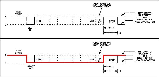
just had a look at the start and stop bit framing for RS232 data, and found the following:
the top diagram is the original, the bottom has the levels for sending a zero byte (chr$(0) in MMbasic) with no parity highlighted in red. on the face of it, it appears that you get a single clean negative-going pulse that is 9-bits long.
if this was inverted with a single transistor, would the single positive pulse not be ok for PGC? adjusting the baud rate, one could selected a desired pulse length. it would still be necessary to monitor using RI or CD to be sure the pulse was finished (plus wait for a couple of bit-times for the stop pulse to pass) before moving on to send out the next ICSP bit.
someone with a digital scope to hand might care to check this out.
this doesn't address the issue of assuring that the PGD data is synchronised. it could be worth an experiment though, to see what happens. perhaps PGD could be monitored with another spare input line?
rob :-)Edited by robert.rozee 2014-08-31
JohnS Guru Joined: 18/11/2011 Location: United KingdomPosts: 4335
Posted: 01:41am 30 Aug 2014
Copy link to clipboard
Print this post
How have you allowed for the ms delays of indeterminate length?
Are you thinking maybe 1 baud?
It looks unreliable and much slower than what I have now!
This is the system:
PC with USB host ========= USB serial I/O board ====== RS232 lines ==== PIC32
Everything, every tiny I/O, needs at least a packet taking multi-ms from PC to USB serial board. Any I/P requires at least one return packet as well.
JohnEdited by JohnS 2014-08-31
robert.rozee Guru Joined: 31/12/2012 Location: New ZealandPosts: 2528
Posted: 01:52am 30 Aug 2014
Copy link to clipboard
Print this post
it may well be less than reliable. i am just kicking around the idea. it may also require some tricks using windows (or linux) interrupts to ensure that everything happens at the right time; basically, every change of PGD would need to be confirmed before the next PGC pulse was triggered. i honestly have no idea how much overhead would be required to do that.
rob :-)
JohnS Guru Joined: 18/11/2011 Location: United KingdomPosts: 4335
Posted: 01:56am 30 Aug 2014
Copy link to clipboard
Print this post
Please see my pic above. To do what you ask it must be done on the USB board as there are NO interrupts at all from the RS232 lines into the PC. It's all USB packets between PC & USB serial board.
Your kind of idea needs several extra USB packets per minute (as in tiny) transaction so will take forever.
JohnEdited by JohnS 2014-08-31
robert.rozee Guru Joined: 31/12/2012 Location: New ZealandPosts: 2528
Posted: 02:34am 30 Aug 2014
Copy link to clipboard
Print this post
yep, you are right - any (faked) interrupts coming back would follow a long and indeterminate path who's length could not be relied upon. everything would quickly fall to pieces.
another tack: is it fair to assume that the order of outgoing USB transactions is always maintained? ie, if you send an instruction to change the state of (say) DTR, then send another instruction to transmit chr$(0), will DTR change state before the chr$(0) is transmitted?
if this holds true, then perhaps one can simply make sure that bits are 'pumped' out of DTR at a sufficiently slow rate, using a timer interrupt. ie, place PGD bits into a queue, and have a timer interrupt:
1. pick up one bit at a time from the queue
2. set PGD accordingly
3. send a chr$(0) out the comm port
the interval of the timer interrupt would need to be somewhat more than the length of the transmitted byte, and one could start very slow and experiment with ramping up the rate. using a baud rate of 1 M-bit/s, the length of PGC pulses would be around 10uS.
rob :-)Edited by robert.rozee 2014-08-31
Page 18 of 28
Print this page
The Back Shed's forum code is written, and hosted, in Australia.


 I have been absorbing/translating/guessing this document for the last two months which is exactly why I 'hint' that your code would make a useful 'cross reference' to use to check against the steps I use in my code. I was just hoping you might wish to share your 'hard work'