
|
|
Forum Index : Microcontroller and PC projects : PicoMite: PicoGAME VGA development
| Author | Message | ||||
| al18 Senior Member Joined: 06/07/2019 Location: United StatesPosts: 238 |
Phill, Mick, Thanks for the pointers. I checked all the Resistors and diodes in the VGA circuit individually, but not from the Pico pins thru the VGA connector. I will do some more measuring with power off and disconnected. I can also compare with the reading from the PicoMiteVGA board - must be something I�m missing. The PicoMiteVGA board displays all 16 colors. I have deviated from the BOM by using the MCP1701 150 mA regulator. I measured the voltage test points on the corner of the board and getting 3.3v on the 3.3v test point and about 4.5v at the 5v pad - which seems reasonable since the power is going thru D1. I�m also not happy with the tiny wire Gauge used to supply power to the screw terminal on the board - I�ll try another cable. |
||||
| Mixtel90 Guru Joined: 05/10/2019 Location: United KingdomPosts: 8904 |
Having a low 5V supply will only affect a PS/2 keyboard. The regulator is apparently supplying 3V3 so there must be enough overhead for it (although there's not a lot to spare). Have you done the mod to ground 3V3EN? You should do. The circuit of the V1.4 board is the same as Peter's as far as the video and keyboard go, with the exception of the trimmer pot. I advise you to check for short circuits (as I listed above) and dry joints before you even consider plugging a PicoMite in again and powering up. Check pin to adjacent pins as well as pin to ground for every pin in that area. None of the traces in the video circuit go very far so they are easy to follow. I assume you're using a known good VGA lead? I know it's a silly question. :) Mick Zilog Inside! nascom.info for Nascom & Gemini Preliminary MMBasic docs & my PCB designs |
||||
| al18 Senior Member Joined: 06/07/2019 Location: United StatesPosts: 238 |
Ok thanks. I may just start building a second board starting with the VGA circuit to help with the troubleshooting. My back order of MCP1700 arrived two days ago. I bought extra of everything, including the Pico. Edited 2022-05-24 01:46 by al18 |
||||
| Mixtel90 Guru Joined: 05/10/2019 Location: United KingdomPosts: 8904 |
Well, I know Version 1.4 works because I was writing a program on one last night. It even works without C2, which I never got round to fitting. :) Version 1.4A has a minor mod to the incoming power supply and some caps added to the audio - it's identical in other respects. The VGA circuit is very simple. You say that you only get 8 colours in the test program. Which ones are wrong? That would tell us which of the 4 output bits is wrong. Loss of GP19 (Green Low) will make white appear lilac. Loss of GP20 (Green High) will make white appear fuchsia. The 220R resistors will almost certainly protect the PicoMite pins against damage, even if you get short circuits on the other end. If the monitor is failing to detect a VGA input then it's probably one of the synch signals that it can't see. The colour signals are constantly changing and can even remain as black. One of them is either open circuit or shorted to something else, such as GND. That's not good for the PicoMite as there is no protection on those signals. Mick Zilog Inside! nascom.info for Nascom & Gemini Preliminary MMBasic docs & my PCB designs |
||||
| al18 Senior Member Joined: 06/07/2019 Location: United StatesPosts: 238 |
On your test program, the lilac button was white. White appears white. I believe the brown button was yellow. I�ll figure it out. I like the board design and I located a dpdt toggle switch, so I can switch between audio high and audio low. |
||||
| Mixtel90 Guru Joined: 05/10/2019 Location: United KingdomPosts: 8904 |
For lilac to appear white and brown to appear yellow bit 1 has to be stuck high. That's the green low signal (GP19). Now, it could be stuck high but to do that you'd need a pretty big solder blob underneath - one that you would notice! On the other hand, if R17 was open then GP19 may not pull as low as expected. Reflow both ends of it. I like the idea of a switch - I almost considered putting a slide switch onboard. The problems are that they are not easy to get in small sizes and I'm a bit doubtful about the longevity of the contacts on them. I figured that most people will leave it in one position anyway. :) Mick Zilog Inside! nascom.info for Nascom & Gemini Preliminary MMBasic docs & my PCB designs |
||||
| phil99 Guru Joined: 11/02/2018 Location: AustraliaPosts: 3289 |
Here is the simplified DAC I use. Dark Green and Mid Green are not exactly the same as the precision DAC but with only two bits the colours will always be as rough as guts no matter what is used. 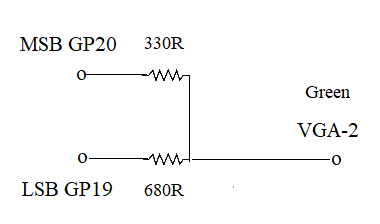 If all else fails remove the existing resistors and use this. It will give all 16 colours. |
||||
| Tinine Guru Joined: 30/03/2016 Location: United KingdomPosts: 1646 |
Hey Mick, Is this correct? I don't get these GP assignments on the full-size SD card: 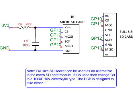 Craig |
||||
| Tinine Guru Joined: 30/03/2016 Location: United KingdomPosts: 1646 |
SPI TX = MOSI (master-out-slave-in): GP3,GP7,GP11,GP15,GP19,GP27 SPI RX = MISO (master-in-slave-out) GP0,GP4,GP8,GP12,GP16,GP20,GP28 Unless I misunderstand (it happens a lot  ) )Craig |
||||
| Mixtel90 Guru Joined: 05/10/2019 Location: United KingdomPosts: 8904 |
There isn't a problem as on the MicroMite the SDcard is always software driven and doesn't use the SPI hardware built into the chip. Even if you use SYSTEM SPI the SDcard will still use software. You can actually use any pins you like for an SDcard. :) This is why I was able to simply reverse the order of the OPTION SDCARD signals to allow an alternative full size SDcard to the micro SDcard module, which has the socket upside down. Edited 2022-05-25 19:25 by Mixtel90 Mick Zilog Inside! nascom.info for Nascom & Gemini Preliminary MMBasic docs & my PCB designs |
||||
| Tinine Guru Joined: 30/03/2016 Location: United KingdomPosts: 1646 |
Aha...That's what the other thread was referring to when they said it was bit-banged  Craig |
||||
| Mixtel90 Guru Joined: 05/10/2019 Location: United KingdomPosts: 8904 |
Correct. :) The next version of the PicoGAME allows a SMD microSD socket, as well as a full size one. The pins are in the same order so it wasn't difficult to do. Mick Zilog Inside! nascom.info for Nascom & Gemini Preliminary MMBasic docs & my PCB designs |
||||
| Tinine Guru Joined: 30/03/2016 Location: United KingdomPosts: 1646 |
Did I see blind vias on the pics? Pretty sure I read that JLCPCB don't support them. �  Craig Edit: Good call on the Toby Electronics, BTW They have stuff that makes me wanna part with money Edited 2022-05-25 21:16 by Tinine |
||||
| Mixtel90 Guru Joined: 05/10/2019 Location: United KingdomPosts: 8904 |
Nope, no blind vias. There's no solder mask on them though. Actually, there are no blind vias anyway as they don't exist on 2-layer boards. A true blind via can link internal layers and not show on the outside. Mick Zilog Inside! nascom.info for Nascom & Gemini Preliminary MMBasic docs & my PCB designs |
||||
| lizby Guru Joined: 17/05/2016 Location: United StatesPosts: 3782 |
Did I miss a recent release? Mick--could you add another line to your signature for a link to your PCBs? It can be hard to keep track of where the latest and greatest is. PicoMite, Armmite F4, SensorKits, MMBasic Hardware, Games, etc. on FOTS |
||||
| Mixtel90 Guru Joined: 05/10/2019 Location: United KingdomPosts: 8904 |
It went 1.4 then 1.4A, that's all. There's been no more releases since. I'm still playing with the next version. :) Mick Zilog Inside! nascom.info for Nascom & Gemini Preliminary MMBasic docs & my PCB designs |
||||
| Tinine Guru Joined: 30/03/2016 Location: United KingdomPosts: 1646 |
Perusing the thread, late last night, I believe that you stated that you had changed the VGA circuitry but based on the latest schematic, it doesn't appear to be different(?) Craig |
||||
| Mixtel90 Guru Joined: 05/10/2019 Location: United KingdomPosts: 8904 |
No, I've not changed it. The prototype, 1.4 and 1.4A all use the same basic circuit as Peter's original. The only minor change I have used is a fixed resistor in series with a variable instead of a 200R trimmer. It gives a narrower range of adjustment with no possibility of short-circuiting the green output. You can still fit the 200R trimmer instead if you like. There is a place for it on the pcb. Phil has suggested using a simple resistor pair instead of the R-2R ladder for green, but I've not implemented it. I did on the PicoMite Keyboard to save on board space, but I've not built one and I don't know how effective it is. I also used it on the PicoMite Pear, but no-one has even considered building that yet. :) �(I've not posted the latest gerbers for that yet. See the "Should I call this one Gemini?" topic.) Edited 2022-05-25 22:50 by Mixtel90 Mick Zilog Inside! nascom.info for Nascom & Gemini Preliminary MMBasic docs & my PCB designs |
||||
| Tinine Guru Joined: 30/03/2016 Location: United KingdomPosts: 1646 |
This has inspired me to add a fith processor to my system Now I have 8 processors in the Parallax P2 and 5 processors running MMBASIC I prefer the PGA-2040 to the Pico. Just received 10 more units. Craig |
||||
| lizby Guru Joined: 17/05/2016 Location: United StatesPosts: 3782 |
Could you provide a link? PicoMite, Armmite F4, SensorKits, MMBasic Hardware, Games, etc. on FOTS |
||||
| The Back Shed's forum code is written, and hosted, in Australia. | © JAQ Software 2026 |
