
|
|
Forum Index : Microcontroller and PC projects : Stepper Project
| Author | Message | ||||
Bryan1 Guru Joined: 22/02/2006 Location: AustraliaPosts: 2155 |
Phil the top of the spring is held by a 1/4" cap screw where a hole on each side were the same height so it made it easy to hook up  Now to adjust the spring all I need to do is drill/tap more holes for different spring setting. Now to adjust the spring all I need to do is drill/tap more holes for different spring setting. |
||||
| Bryan1 Guru Joined: 22/02/2006 Location: AustraliaPosts: 2155 |
Ok found the first problem with claudes code as I have the controls set to 75 and the code goes upto 79. So changed the gui controls to 80 and uploaded again. [148] VAR save SurGrind, SV.PosX, SV.PosY, SV.PosZ, SV.XLen, SV.XFeed, _ Error : Cannot find SURGRIND Now I did try commenting out OPTION EXPLICIT but the same error comes up so it does look like SURGRIND isn't declared so whats the correct way to get this done please as the grey cells are calling for more caffine. |
||||
| Bryan1 Guru Joined: 22/02/2006 Location: AustraliaPosts: 2155 |
OK after some caffine intake I put in dim float SurGrind Then got to the next error where the VAR SAVE was over 3 lines so had to put the VAR SAVE SurGrind, on the lower 2 lines No errors so now I can have a play and the page 7 run screen does look nice |
||||
| Bryan1 Guru Joined: 22/02/2006 Location: AustraliaPosts: 2155 |
One thing I have noticed is the position display box's aren't being filled and I'm sure this SUB Sub SAVE_VARS SV.PosX = Peek(stepper X) SV.PosY = Peek(stepper Y) SV.PosZ = Peek(stepper Z) SV.XLen = CtrlVal(XPOS) SV.XFeed = CtrlVal(XFPOS) SV.YLen = CtrlVal(YPOS) SV.YFeed = CtrlVal(YFPOS) SV.ZLen = CtrlVal(ZPOS) SV.ZFeed = CtrlVal(ZFPOS) SV.RunZStep = CtrlVal(RUN_ZSTEP) SV.RunZFeed = CtrlVal(RUN_ZFEED) SV.RunZDepth = CtrlVal(RUN_ZDEP) SV.CycleCount = SV.CycleCount + CycleCount ' accumulate across sessions Var save SurGrind, SV.PosX, SV.PosY, SV.PosZ, SV.XLen, SV.XFeed var save SurGrind, SV.YLen, SV.YFeed, SV.ZLen, SV.ZFeed, SV.RunZStep var save Surgrind, SV.RunZFeed, SV.RunZDepth, SV.CycleCount End Sub is the problem as one of the errors was SurGrind wasn't declared so I did declare SurGrind as Float and after doing the var save on the lower 2 lines got no errors but it does seem the the var restore isn't working. So not sure what is going on |
||||
disco4now Guru Joined: 18/12/2014 Location: AustraliaPosts: 1133 |
Hi Bryan1, VAR SAVE is writing to Flash. Not sure how long it would take to wear it out at the rate you are thinking of writing. This I2C RAM chip may be useful. Search 47LS04 is the forum where a few have used it, see Jim's post below for details on using it. An alternative to VAR SAVE 47LS04 F4 H7FotSF4xGT |
||||
| Bryan1 Guru Joined: 22/02/2006 Location: AustraliaPosts: 2155 |
Gerry I do have a heap of old microchip 24AA eeproms here so we could use one of them as I am considering making a new driver board where the breakouts can be spaced 5.08mm so standard connectors can be used. Now this eeprom can sit nice and close to the pico 2 so no interference is there and got plenty to share with Lyle |
||||
| phil99 Guru Joined: 11/02/2018 Location: AustraliaPosts: 3321 |
Another option, if a RTC module is being used, is the 24C32 I2C EEPROM chip that most RTCs are fitted with. It can store 4096 bytes in 128 32 byte pages. |
||||
| Bryan1 Guru Joined: 22/02/2006 Location: AustraliaPosts: 2155 |
Ok I decided to try out Lyle 005 code and did a stepper status > stepper status Armed: YES, Motion: IDLE Auto-disable on idle: OFF S-curve: OFF, Jerk: 50000.0 mm/s^3 Buffer: 0/150 blocks, executed: 0 Position known: YES Planner: X=100.000 Y=50.000 Z=20.000 A=0.000 G92 offsets: X=0.000 Y=0.000 Z=0.000 A=0.000 HW limits: ON, mask=0x000000001c000000, active_high=0x0000000000000000 HW limit pins: Xmin=26 Xmax=26 Ymin=27 Ymax=27 Zmin=28 Zmax=28 X: 100.000 mm (20000 steps) X cfg: step=2 dir=3 en=0 inv=0 spmm=200.000 vmax=7.500(mm/s) amax=500.000 hback=3.000(mm) Y: 50.000 mm (10000 steps) Y cfg: step=4 dir=5 en=255 inv=0 spmm=200.000 vmax=13.333(mm/s) amax=500.000 hback=3.000(mm) Z: 20.000 mm (127600 steps) Z cfg: step=6 dir=7 en=1 inv=0 spmm=6380.000 vmax=100.000(mm/s) amax=500.000 hback=3.000(mm) > Now this is the one with claudes code > stepper status Armed: NO, Motion: IDLE Auto-disable on idle: OFF S-curve: OFF, Jerk: 50000.0 mm/s^3 Buffer: 0/150 blocks, executed: 0 Position known: NO Planner: X=0.000 Y=0.000 Z=0.000 A=0.000 G92 offsets: X=0.000 Y=0.000 Z=0.000 A=0.000 HW limits: ON, mask=0x000000001c000000, active_high=0x0000000000000000 HW limit pins: Xmin=26 Xmax=26 Ymin=27 Ymax=27 Zmin=28 Zmax=28 X: 100.000 mm (20000 steps) X cfg: step=2 dir=3 en=0 inv=0 spmm=200.000 vmax=7.500(mm/s) amax=500.000 hback=3.000(mm) Y: 50.000 mm (10000 steps) Y cfg: step=4 dir=5 en=255 inv=0 spmm=200.000 vmax=13.333(mm/s) amax=500.000 hback=3.000(mm) Z: 20.000 mm (127600 steps) Z cfg: step=6 dir=7 en=1 inv=0 spmm=6380.000 vmax=100.000(mm/s) amax=500.000 hback=3.000(mm) > As the position display won't work may just have to go back to the 005 code and expand that and use the claude example to learn from. now page 7 does invoke the run and the Z axis does step 0.05mm but as we haven't done the code for the buffer yet the run code will do nothing. As the numberbox isn't setup with a decimal point the input can't be less than 1 where on the Z axis we want 0.05 or there abouts. I do think I need to make a new page where one can put in the data so the output can go to the buffer, now I can make the page easily but as far as getting to to work will take a long time to understand. Edited 2026-06-01 16:22 by Bryan1 |
||||
| disco4now Guru Joined: 18/12/2014 Location: AustraliaPosts: 1133 |
The 47LS04 is an EERAM, so no limitation on the number of writes. It can be set to automatically save and restore to/from its own internal EEPROM so it keeps the data during any power interruptions. F4 H7FotSF4xGT |
||||
| Bryan1 Guru Joined: 22/02/2006 Location: AustraliaPosts: 2155 |
Googling the 47LS04 and it's a hex inverter not a ram chip Now this is the datsheet for the 24AA1025's I have here and they can do over a million writes now I do think the amount of times the machine is going to used and the fact we only need to save the position after the job is done the eeprom won't burn out. 24AA1025 Eeprom.pdf Now on further research it's the 47L04 47L04_47C04_47L16_47C16_DS20005371D.pdf Edited 2026-06-01 16:39 by Bryan1 |
||||
| Mixtel90 Guru Joined: 05/10/2019 Location: United KingdomPosts: 8964 |
VAR LOAD doesn't count, that can be ignored. VAR SAVE is one erase/write cycle per grinder operation. At 10 operations per day that would work out at a lifetime of about 27 years before you would need to replace a flash chip or a Pico. (based on 100,000 writes, which may be conservative) Data retention on either is probably around 25-50 years so, basically, VAR SAVE should last at least half the lifetime of the Pico. Or you could note down the co-ordinates on a bit of paper. :) Mick Zilog Inside! nascom.info for Nascom & Gemini Preliminary MMBasic docs & my PCB designs |
||||
| ville56 Guru Joined: 08/06/2022 Location: AustriaPosts: 550 |
That is the reason why we need printer support im MMBasic. No manual notes of variable content anymore !!  73 de OE1HGA, Gerald |
||||
| Mixtel90 Guru Joined: 05/10/2019 Location: United KingdomPosts: 8964 |
We've got COM ports, all you need is a serial printer. :) Of course, with the extra IO on the RP2350B and the PORT command you can now have Centronics! Mick Zilog Inside! nascom.info for Nascom & Gemini Preliminary MMBasic docs & my PCB designs |
||||
| Volhout Guru Joined: 05/03/2018 Location: NetherlandsPosts: 5994 |
Gerald, You can always get the variable values through the COM port to your development PC and print them. Storage in the pico (flash) has the same reliability as SD cards (10k-100k). That is the A:/ drive, and the VAR SAVE area. You should evaluate how often you need to store data in non volatile memory before you can make a decision. When it is once per few minutes, flash inside the PICO will be fine for years. When it is often (once per second, or even several times per second) external storage is needed. But you have to evaluate how much pico CPU time you can spare to do the store. Most external devices will require 1 MMBasic operation to store one variable (with several parameters). That is I2C or SPI. So when you want to save an array or a structure, that is typically a loop of MMBasic commands. And that slows down. You do not want that slow down in a fast control loop. I would personally look for the simplest implementation (the VAR SAVE). It is the fastest, and when you can limit the number of saves, you can use it a loooong time. You can always keep a spare pico if this one starts failing. For that money it is the cheapest solution. Volhout PicomiteVGA PETSCII ROBOTS |
||||
| PhenixRising Guru Joined: 07/11/2023 Location: United KingdomPosts: 2003 |
Hi, I came here from the year 2026 where we don't use paper anymore; we automatically send backups of everything to a device that we keep in our pockets (Bluetooth).  |
||||
| mozzie Guru Joined: 15/06/2020 Location: AustraliaPosts: 403 |
G'day Bryan, No worries there, this is your project after all. To keep it moving forward Claude is probably a good move, as I stated, I have a million projects and work gets in the way of all of them, if you wait for me it'll be a long road indeed. Maybe see how you go with Claude and I will try to help where needed, and I will continue to work on my version, we may be able to blend them together at the end. On that subject, I have been working away in the background on the original code when time allows, this is to add an axis setup page and an axis homing page. This means you home the machine on power up and then it doesn't matter if its moved since the last job, so no need to store positions. Only the Z-axis is causing me problems, a homing switch would not be accurate enough. Axis Config Page: 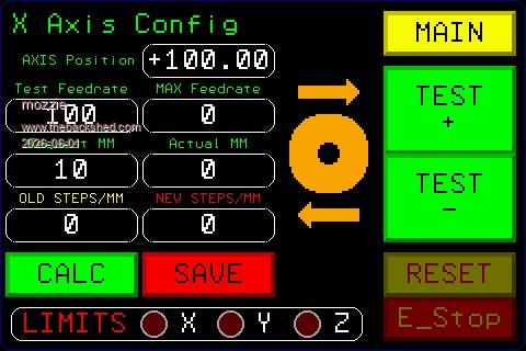 The other problem is I'm trying to make the code work for any CNC so it all takes a lot more thinking about, but I love a challenge. Regards, Lyle. |
||||
| Volhout Guru Joined: 05/03/2018 Location: NetherlandsPosts: 5994 |
Hi Lyle, Touchscreens (also the small ones) tend to get very smudged by oily hands on CNC's. I don't know why... And they become hardly readable. Maybe you should avoid small fonts, and dark colors (single pixel dark green/red on black). The big buttons are fine. The E-STOP should be a hardware button (touch is not reliable enough to save lives/hands/fingers). Those are my 5 cents. Volhout PicomiteVGA PETSCII ROBOTS |
||||
| Mixtel90 Guru Joined: 05/10/2019 Location: United KingdomPosts: 8964 |
Agreed. There may not be a display (or even a Pico) when an ESIOP is needed. Also, you may not be adjacent to the control panel, you (or a potential rescuer) may be closer to the door attempting to avoid shrapnel. That's what ESTOP loops are for. I even put a latching button right by the door in my shed to kill all the supplies. Mick Zilog Inside! nascom.info for Nascom & Gemini Preliminary MMBasic docs & my PCB designs |
||||
| mozzie Guru Joined: 15/06/2020 Location: AustraliaPosts: 403 |
G'day, Motorcycle visor "Tear-offs" are a great way to stop the magical ingredients in cutting fluid destroying the touch screen, also have some capacitive versions to try These 4" displays are a nice compromise, larger would be better but the config screen shown is rarely used and the main screens have the larger buttons. The "E-Stop" is just an indicator for the wired E-Stop system, hence the reason it is shown disabled, the loop is intact. The "RESET" does as its name suggests once the system is in a suitable state. Regards, Lyle. |
||||
| Mixtel90 Guru Joined: 05/10/2019 Location: United KingdomPosts: 8964 |
Ah. :) Does clingfilm work on the displays? I've used it on those tools that have "non-slip grips" that go all sticky and yucky. Mick Zilog Inside! nascom.info for Nascom & Gemini Preliminary MMBasic docs & my PCB designs |
||||
| The Back Shed's forum code is written, and hosted, in Australia. | © JAQ Software 2026 |
