
|
|
Forum Index : Microcontroller and PC projects : simplest 32MX150 ICSP
| Author | Message | ||||
| JohnS Guru Joined: 18/11/2011 Location: United KingdomPosts: 4335 |
Ignoring the very real problem of timer interrupts (neither Windows nor Linux provides such interrupts to user programs), to send a bit on DTR needs a USB packet. To send a chr(0) needs another USB packet. Yes they'll occur in the order commanded. At the moment I use bits on a small number of pins and can send all out with one packet (i.e. any/all of MCLR, PGC, PGD, being on CTS, DCD, DTR). Doing it as you suggest looks to need at least 2 packets per bit so would be half as fast at best. (And you'd have to have pretend interrupts, which can crudely be done using a separate thread and timers but will be painful and async to the packets i.e. could come before, during or after any of the packets. Nasty. Very.) John |
||||
| robert.rozee Guru Joined: 31/12/2012 Location: New ZealandPosts: 2528 |
does PGC clock data out on both the leading and trailing edges? while true timer interrupts don't get exposed to the user, most modern operating systems do provide a 'faked' version (often called a multimedia timer) that can achieve an irregular interrupt close to the user set rate, with an interval no less than what the user program requests. ie, ticks get dropped, with no attempt to catch up. there are also microsecond os delays available to 'roll your own'. but i've thought up a few more problems that might prove inelegant / too complex to get around. still, it was a nice thought experiment; at the least, it suggest that a serial port output (even on a micromite) could be used as a pulse generator. do you know roughly how many bits-per-second you achieve out of PGD? rob :-) |
||||
| JohnS Guru Joined: 18/11/2011 Location: United KingdomPosts: 4335 |
As I understand Mchp datasheet (which is unclear), no. I don't see any help from a (fake) interrupt even if it wasn't async wrt the USB (which it is). Not something I wish to contemplate programming. No idea but it programs a full micromite depending on the PC (& OS) in 15-55 mins. You could look at Mchp datasheet and figure it out. Roughly 100KB, sending a word at a time via PE's ROW_PROGRAM. Roughly, that calls XferFastData for each word (and various other stuff but ignore that). See the Mchp doc. I need to do other things so please read the doc. John |
||||
| robert.rozee Guru Joined: 31/12/2012 Location: New ZealandPosts: 2528 |
right... after a few hours of further contemplation i have an idea to throw out there to everyone, a possible method of generating both PGC and PGD from just the TxD output of any ttl-level usb to serial bridge. by setting the serial port to 1Mbps (no parity, 1 stop bit) it looks like we can generate a quite precise 1uS negative-going pulse on TxD by sending chr$(255) out the serial port, and a 10uS pulse by sending chr$(0). lets take the TxD output and feed this into the trigger input (pin 2) of a LM555 configured as a 5mS monostable oscillator. note that the TxD output idles at logic '1', while the 555's trigger input responds to a falling edge. 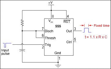
if a 1uS trigger pulse is used, the rising edge on the TxD line will coincide with the output of the monostable being '1' (high). if a 10uS pulse is used, the rising edge on the TxD line will coincide with the monostable output being '0' (low). we therefore just need to connect TxD to PGC as well as the 555's trigger input, and feed the 555's output (pin 3) to PGD via a 3k3 resistor. PGD data can be read back directly on the pin using one of the RS232 port's spare flow control inputs, as has already been well proven. the LM555 officially runs down to 4.5v, but cmos versions are available that work down to a couple of volts. the trigger input trips at 1/3Vcc, with the device drawing just a few milliamps. i'd in fact expect most regular LM555's to function fine at 3.3v with little issue. the above should produce a sustained PGD bit rate of 100,000bps. if the port can be set to 5-bits instead of 8, this could be boosted by around 30%. if desired, TxD can also be looped back into RxD, allowing a linux/windows application to count the data going out so as to know when a valid value can be read back from PGD. comments anyone? rob :-) |
||||
| hitsware Guru Joined: 23/11/2012 Location: United StatesPosts: 535 |
I haven't a clue what accuracy you need, but t is dependent on the precise values of R & C A PicAxe might be more accurate ? |
||||
| robert.rozee Guru Joined: 31/12/2012 Location: New ZealandPosts: 2528 |
we're looking at two substantially different pulse lengths: 1uS versus 10uS, so the monostable could vary between 2uS and 8uS without causing an issue. the LM555 itself is very stable and timing is independent of temperature and supply voltage variations, while R and C should be within 10% for most off-the-shelf parts over quite a temperature range. bottom line: a 555 + R + C is unlikely to be any more than 20% off in the worst case, which won't matter at all. (actually, with no parity, the long pulse will only be 9uS. but that doesn't matter) rob :-) addendum 1: the TI datasheet for the 555 states, "In monostable operation, the trigger should be driven high before the end of timing cycle". to achieve this, a suitable RC network will need to be added before the trigger input. addendum 2: looks like PGD is clocked in/out on the falling edge of PGC. a second simple RC network should suffice to shape the rising edge on TxD into a short pulse to accommodate this. |
||||
| G8JCF Guru Joined: 15/05/2014 Location: United KingdomPosts: 676 |
Hi On Page 39 of "PIC32 Flash Programming Specification" (DS60001145N) section 16.2.13 GET_DEVICEID COMMAND, it says that the expected response is 1 word, consisting of 16 MSBits containing the "Last Command", ie 0x000A, and 16 LSBits containing the "Device ID", the question I have is that when I execute this PE Opcode, I get back &Ha0010, the 16 MSBits are correct, ie 0xA, but what do the 16 LSBits mean, ie 0x0010, AND, I thought the Device ID was a 32 bit number such as &H26610053 so how does the PE fit a 32 bit number into 16 bits  and/or is the PE's version of the Device ID different from the value stored in the DEVID register and returned in response to MTAP_IDCODE ? and/or is the PE's version of the Device ID different from the value stored in the DEVID register and returned in response to MTAP_IDCODE ?
I must be missing something, could somebody please put me out of my misery and enlighten me ? Very many thanks Peter The only Konstant is Change |
||||
| robert.rozee Guru Joined: 31/12/2012 Location: New ZealandPosts: 2528 |
here goes a more complete schematic of what i was talking about earlier: 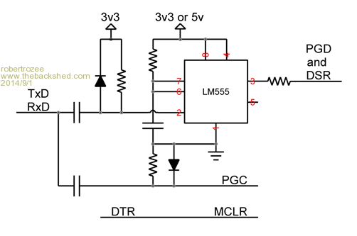
with the comm port set to 1Mbps, 8 bits, no parity: 1. transmitting chr$(0) should create a 9uS negative-going pulse at TxD and cause a '0' to be clocked out to PGD; 2. transmitting chr$255) should create a 1uS negative-going pulse at TxD, causing a '1' to be clocked out to PGD. by counting in the character echoed back on RxD, when it is desired to read back from PGD a program just has to pause until count out = count in (ie, for all Tx buffers to empty out), then read back PGD using the DSR input. DTR is used to handle driving the MCLR line as before. how it works: TxD idles at '1', and goes to '0' at the start of transmission. how long it stays low depends on the character being trasmitted: 10uS for all zero bits, only 1uS for all one bits (chr$255). the falling edge passes through the top RC/diode network creating a short pulse. this initiates a 5mS high-going pulse at pin 3 of the LM555. this output is fed into PGD via a 3k3 ressitor so causing PGD to be set to '1' for the first 5uS after TxD goes low, then back to '0' thereafter. if TxD goes high after 1uS, this rising edge creates a short pulse (via the lower RC/diode network) at PGC. the pulse then clocks in the '1' on PGD. if TxD instead doesn't go high until after 9uS, the clock pulse occurs well after the monostable has reset, and a '0' will be clocked into PGD. in theory, and assuming that PGD needs to be read back infrequently, this should allow a sustained throughput of around 100,000 PGD bits per second. i'd be keen for someone to have a play with this circuit. i'd also be interested if anyone using John's software could attach a piezo sounder to PGC and report back what they hear during programming using the FT232R/resistor solution. this will give an idea of what the achieved bitrate is. cheers, rob :-) |
||||
| JohnS Guru Joined: 18/11/2011 Location: United KingdomPosts: 4335 |
I've been suffering troubles... Running the C code to program PIC32s on an 80MHz PIC32 I had to add a few delays, then it worked when programming an Olimex MX220 (has a 44-pin 220F032D) board. But it didn't work with a BV502 (has the same chip as a Micromite, a 44-pin 150F128D). I've had to add small delays (a few us) in new places and I don't really know why. I have various wires (about 6" long) strung between the board doing the programming and the target's ICSP. Is it liable to be noise / crosstalk? If it is, do I just stick with marginally slower or try something else (what)? Ideas anyone please. It's taking 30 secs to program a Micromite, which seems a bit slow. John |
||||
| G8JCF Guru Joined: 15/05/2014 Location: United KingdomPosts: 676 |
30 secs !!! The only Konstant is Change |
||||
| robert.rozee Guru Joined: 31/12/2012 Location: New ZealandPosts: 2528 |
try the following: 1. read TDO before the rising edge of the 4th clock pulse. 2. if still having trouble, try adding a significant delay before doing the read to ensure everything has settled. i believe that TDO is placed on PGD on the falling edge of the 3rd clock pulse, and can not be guaranteed to be present after the rising edge of that 4th clock pulse. there may also be an issue with out-of-order events when reading back the control line status from the FT232RL - writes may be queued and a read could overtake them. last night i read through the whole of this thread again, then read chunks of the 61145N datasheet relating to the hardware level of talking to the 32MX. rob :-) |
||||
| Keith W. Senior Member Joined: 09/10/2011 Location: AustraliaPosts: 118 |
John, What I am proposing here may not influence what you are suffering, but here goes. I think that you are trying the PIC32 method and not using the USB chip directly to ICSP? Is it that when using the faster processor the ICSP pulse widths are becoming too short, you had indicated that it was taking just a few seconds to program when first using the PIC32. This suggests that the delays that you are now adding when using faster processors are not in the required/optimum place as you would imagine that only the processing speed has changed and that the overall result should not be slower than achieved before? Are you able to slow the new processor to the earlier clock rate for a test that it is only the speed influence? Further: - With the method of using a resistor to couple between chip output and inputs a small delay is introduced into the signal between the programmer output and the subject chip due to the input capacitance of the subject chip input and of the pin reading back the TDO, which must both be charged or discharged via the 3K3 resistor. Any stray capacitance in the wiring will also add and may vary with different chips used and be careful that the resistor used is not also inductive. This RC time constant may become a limiting factor when incorporating the resistor method with fast timing. The input capacitances are small but the 3K3 relatively large. About this resistor value must be retained to protect the drivers. Trying to monitor the signal with an oscilloscope will certainly aggravate any capacitance problem due to the probe input capacitance; however this test may confirm that the capacitance is a problem. I have seen circuits that used a resistor driving an input with no added capacitor as a delay method. The alternative method of turning the programming output pin to an input requires a little more programming but may prove overall faster in practice. A separate pin can still be used for reading back as per the resistor method to minimize software changes for now. I know that you will overcome this frustrating problem. Keith. |
||||
| JohnS Guru Joined: 18/11/2011 Location: United KingdomPosts: 4335 |
Yes, this is a PIC32 programming another (target) PIC32. Thanks all for the replies! I'll have a look at when it is that I treat TDO/TDI as stable and concentrate delay(s) around it. I'd not thought about the resistor's delay / RC time. I'd been hunting for timings in Mchp datasheets with little outcome as regards delays needing to be added to my code. Dropping the resistor and using a bidirectional pin may be worth trying and actually a little faster, too, if the delays can be removed. John |
||||
| JohnS Guru Joined: 18/11/2011 Location: United KingdomPosts: 4335 |
With a 3K3 resistor that should mean a max 1mA so couldn't I safely 1. reduce it, say to 1K 2. increase it, say to 6K8 and see what happens in each case? Is there a way to estimate something like the RC or (more usefully to me) the time delay caused by the resistor? It doesn't seem too bad putting in delays of several usecs but it's worrying that I'm guessing at how many usecs... John |
||||
| Keith W. Senior Member Joined: 09/10/2011 Location: AustraliaPosts: 118 |
John, Well there is any number of unknowns. You could try a lower value resistor. You could look up the input capacitances of the chips and try to calculate the time constant but the best way to determine if the resistor is the problem is to change the code to remove it. If the same �clock� routine is called universally this is not a great change. Do you have an idea of the pulse timing, as determined with an oscilloscope? If the C compiler has done a good job, with an 80 MHz CPU clock the complete sequence of 4 ICSP PCC pulses for a �clock� may be completed in less than 1 microsecond. Based upon about one instruction for every two CPU clocks and probably less than 20 instructions in the tight �clock� subroutine, though because a RISC maybe more. Does the C compiler give an assembly listing of the generated code with clock cycles? The resistor RC delay must be a fraction of the PCC clock time. If you have an oscilloscope you could measure the time of a �clock� sequence by writing a bit of code that calls "clock", waits for a few milliseconds then loops to call �clock� again continuously. This would be interesting to know, it could be that it is just too fast without delays (nops) between each step in the �clock� sequence. I seem to remember that in ICSP mode the subject chip clocks at about just 10MHz but would have to confirm this. At 80 MHz (12.5 ns per cycle) the Pic32 may be clocking the ICSP at a rate that is quicker than the 40 ns pulse hold time from the spec. (page 59?) and I think it safer to be much slower. If someone has a PicKit3 and an oscilloscope we could gain an idea of the ICSP PCC clock rate used there. Keith. |
||||
| JohnS Guru Joined: 18/11/2011 Location: United KingdomPosts: 4335 |
Keith, Thanks. I can't 'scope it (would love to but would also want a storage scope so I could see what the waveforms look like). Due to having the code run on a PIC32 at 80MHz I'm deliberately going via functions so there's no shortage of instructions. The datasheet talks about things like min 40ns and period min 100ns whereas I'm inserting delays (via function calls that spin on CP0COUNT, or whatever it's called, that counts at half cpu clock) of a few us. Looks like taking the resistor out and going bidirectional is the next step. I have ASM listings and my strategy above shows lots of instructions get executed with multiple calls/returns so the cache etc will struggle to achieve much. Oddly (is it?), the olimex MX220 is much less trouble than the ByVac BV502, though I suppose I'm programming about 4 times the bytes into the latter (as it has 4 x the flash). In the PICkit's favour, it's not got 6" wires all over the place between it & the target chip! edit: quick statistic: programming micromite hex is a bit over 6 million low (same number high) PGC transitions John |
||||
| Keith W. Senior Member Joined: 09/10/2011 Location: AustraliaPosts: 118 |
Hi John, I am sorry to be so damn pedantic but have set out below to be sure that we are on the same boat. When I have written about �clock� in quotes as here I mean the 4 phase ICSP sequence as depicted below by the MMBasic code that was shown earlier in this thread. Note that this does not use the resistor method which will eliminate a few steps regarding changing pin I/O direction. 'create 4 phase clock and read data out on PGED line Sub clock(tdi,tms) Pin(clk)=1 'first clock SetPin pgd,dout 'Programmer PGED output on Pin(pgd) = tdi Pin(clk)=0 'latch tdi into chip Pin(clk)=1 'second clock Pin(pgd) = tms Pin(clk)=0 'latch tms into chip SetPin pgd,din 'as chip tdo active soon Pin(clk)=1 'third clock Pin(clk)=0 'enable chips TDO tdo=Pin(pgd) 'as data was ready after fall of clock 3 Pin(clk)=1 'fourth clock Pin(clk)=0 End Sub In looking for a speed related problem I am supposing that it is just the execution of this routine that is troublesome. Other things to try are not obvious. I had assumed that the overhead in calling this routine is slow enough to not be the problem but it does get called again immediately repetitively when programming. That could be tested by placing a temporary small delay within the beginning of it. I suppose that you have a similar routine within your code. Because of the repetitive use it is natural to make it as tight as possible. However when translated to machine code there may be only 1 instruction executed between the output pin transitions, not sure with a PIC32. At 80 MHz this is too fast. This routine is self contained and does not call anything so I am not sure about the method you have used to introduce delays affecting anything here. If you can look at the generated code for just this routine I think that it would be fairly short. To slow this down delays must be introduced between EACH step within this routine. In assembler one would place nops within the code or simply repeat instructions to slow it down which will not change operation otherwise. It should be possible to slow this to the extent that the resistor can play no greater part than with the slower processor, though it may still be worth eliminating it. I was not sure about the delays that you were adding. I cannot believe that the code must run slower overall than when successfully programming previously. At the clock rates used here cable lengths and stray capacitance are important and I would not use the resistor method, 80 MHz is in the VHF band. Keith. |
||||
| robert.rozee Guru Joined: 31/12/2012 Location: New ZealandPosts: 2528 |
john, a page i keep going back to contains this note: "We recommend filtering the PGD output from the target PIC by adding 100 Ω in series followed by 47-100pF to ground. This limits the slope of edges and attenuates the high frequency components that can couple from PGD to PGC. We also recommend adding the same capacitance to ground to the PGC line close to where it enters the target board by the programming connector. This reduces the impedance of the PGC line at high frequencies, which reduces its susceptibility to crosstalk." http://www.embedinc.com/picprg/icsp.htm although it does contain a couple of dubious points, it is well worth a read and may explain some of the problems you are seeing across different boards. rob :-) |
||||
| Keith W. Senior Member Joined: 09/10/2011 Location: AustraliaPosts: 118 |
Rob, Good find, but in the note you have posted I think that the clock rates used are slower. In the PicKit3 User Guide there is mention of crosstalk but it is suggested that separating the wires and keeping short most always corrects the problem, no mention of capacitors. The PickKit3 uses a 12 MHz CPU crystal, likely to suit the USB port. Perhaps the PIC24FJ256GB106 internal can clock at multiples of this but maybe not, rated to 32 MHZ. The clock and data to ICSP are driven by high speed tri-state 74LV1T45 buffer chips with resettable 50 mA polyfuses in series to the ICSP pins, which will have less than 10 ohm resistance till tripped. There is a clamping diode and a 4K7 pull down resistor on the buffer I/O pin. The buffers also allow for level translation to different logic voltage levels. Keith. |
||||
| Keith W. Senior Member Joined: 09/10/2011 Location: AustraliaPosts: 118 |
Duplicated!! |
||||
| The Back Shed's forum code is written, and hosted, in Australia. | © JAQ Software 2026 |
