
|
|
Forum Index : Microcontroller and PC projects : Electronic heater plate....
| Author | Message | ||||
palcal Guru Joined: 12/10/2011 Location: AustraliaPosts: 2039 |
NEAT Paul. Edit. Out of interest what eggs are you hatching. "It is better to be ignorant and ask a stupid question than to be plain Stupid and not ask at all" |
||||
GoodToGo! Senior Member Joined: 23/04/2017 Location: AustraliaPosts: 188 |
I find a frypan full of water delicately heated by a gas burner brings out eggs just nicely.........  GTG!  ...... Don't worry mate, it'll be GoodToGo! |
||||
| Phil23 Guru Joined: 27/03/2016 Location: AustraliaPosts: 1667 |
Shhhh, They are probably Dragons.... Destined for the next GOT Series. |
||||
| CaptainBoing Guru Joined: 07/09/2016 Location: United KingdomPosts: 2171 |
I'm going a different way... a few of these - 12V 1Amp they easily get too hot to touch with no heatsink (your plate), monitor the temperature and PWM them really easily. Two plus points: 1. visual indication it is working 2. would look really cool my 2p |
||||
| robert.rozee Guru Joined: 31/12/2012 Location: New ZealandPosts: 2499 |
oh no, not dragons! everyone knows that the ministry of magic (called the MBIE here in new zealand) prohibits the breeding of dragons. (for our australian friends, the MBIE is a government department colloquially known as either 'the ministry of everything' or 'the ministry of magic'. it is widely regarded as being evil) cheers, rob :-) |
||||
redrok Senior Member Joined: 15/09/2014 Location: United StatesPosts: 209 |
Hi Grogster; Please clarify a couple of things: 1. What is the power source? 120VAC, 240VAC, or a lower DC voltage? 2. What is the desired maximum heater power in Watts? 3. Once up to temperature what is, roughly, the normal running heater power? 4. What is the normal ambient temperature? 5. What is the desired plate operating temperature? redrok |
||||
Azure Guru Joined: 09/11/2017 Location: AustraliaPosts: 446 |
what about one of these Egg Incubator Heater Element in 110v or 220v |
||||
Grogster Admin Group Joined: 31/12/2012 Location: New ZealandPosts: 9932 |
@ redrok: 1) 12v ideally, but will settle for 24v. Has to be portable, with battery backup. Mains for charging the batteries or indoor use is fine. 24v pad will draw 6A or so while on, which is manageable. 12A for the 12v one might be pushing the life expectancy of the gell-cell! 2) Don't care. All I need, is to be able to EVENLY heat up the 3mm plate to about 45-ish Celsius and keep it there. There is a foam layer on top of the plate, that the eggs sit in to keep them warm, then another layer on top of that, then you close the lid. Eggs never actually TOUCH the plate, as it's surface temperature is too hot(for the eggs), but cos of thermal lag, the plate needs to be about 10'C hotter then you want it to be on the top of the foam. 3) Off. Heater just warms up the plate, then switches off and on to maintain that temperature. Nothing fancy. 4) Can be anything from zero to 30'C. Eggs can be collected at any time of day or night, any time of year - just whenever the hives are ready. 5) See #2. But needs to be adjustable. Having said that though, generally you set-and-forget. @ Palcal and others asking about eggs: Velociraptor. It'll be fine - they are all female so won't breed..... But seriously, queen-bee eggs. They can be collected from the hives at any time, and as the hives can be far away from any power source, the unit has to be battery powered so the eggs can be collected from the hive, and transported to the hatchery. If the queen-bee eggs drop below about 33-35'C, the cold kills them. @ Azure: Nice element. Just bigger then the wee ones I was looking at yesterday. But cannot be mains powered, must be battery powered for portability. Smoke makes things work. When the smoke gets out, it stops! |
||||
| redrok Senior Member Joined: 15/09/2014 Location: United StatesPosts: 209 |
Hi Grogster; Very interesting project! You know more about what is needed for building the carrier and caring for the little beasties. 1. The rubber heaters are the way to go silicone glued to the plate. They heat the plate evenly without hot spots. Their relatively cheap and come in a wide array of sizes. Also thin and light weight. They are available in any wattage density and voltage. I might suggest the heater power rating be about 3 times the running power when up to temperature. 2. The uMITE is perfect using the built in PWM for controlling a MOSFET. Say at 100Hz or so. At this low frequency you could directly drive a sub-logic level MOSFET from a 3.3V uMITE pin. I like the IRF3708. 3. A simple thermister sensor glued to the plate should have a fast reaction to changes in plate temperature. (I normally don't like thermisters but in this case you are controlling to a setpoint they would be easy to use.) 4. I suspect you don't need a full "PID" control routine because there will be little thermal lag between the plate and the thermister, pluss you have an insulator between the plate and the little critter's. The "P" part of PID directly controls the PWM from 0% to 100% over about 1 deg C. If you want to limit the heater power reduce from 100% to some lesser value. 5. 12V so you can plug it into the car's power. redrok |
||||
| Grogster Admin Group Joined: 31/12/2012 Location: New ZealandPosts: 9932 |
Hey there.  I am thinking of getting a 24v pad, but running it on 12v. I don't need anything like the heat they are designed for, so the likes of a 150W @ 24v pad, but run it on 12v, so the current should be about 3A and roughly 75W. The pads I am looking at have a 10k NTC built-in, so that takes care of that! Here is a link to the A4 one I am looking at. 24v, 150W, 3.2-Ohm so Ohm's law tells me that running on 12v, that should be 3.75A, which is about 45W or so, which should be plenty, and it will be an easy life for the pad too I would think.Re #2: Are you saying control the heating pad via a MOSFET and PWM? I think that is what you are saying, but just want to make sure I do understand you right. Smoke makes things work. When the smoke gets out, it stops! |
||||
| redrok Senior Member Joined: 15/09/2014 Location: United StatesPosts: 209 |
Hi Grogster;No no, 37.5W. You have 1/2 the voltage and 1/2 the current = 1/4th the power.I agree.Exactly. The uMITE reads the thirmister, calculates the error from the desired setpoint, and sets the PWM output. The PWM controls the heater power as a percentage of max power. The control loop is plenty fast enough in basic. I might add another thermister to measure the the bee's temperature on the other side of the insulating barrier. This could be a second slow control loop that adjusts the main setpoint a bit, slowly. This, effectively, acts as the "I" or Integrate in "PID". To increase efficiency another insulating barrier could be placed on the "Outside" surface of the plate. Less heat loss = more efficiency and longer battery life. What kind of battery are you considering? How long does this battery need to run before you plug into the car's power? redrok |
||||
| Grogster Admin Group Joined: 31/12/2012 Location: New ZealandPosts: 9932 |
Arrggghhh.  Being on holiday I have let my Ohm's law slip! Being on holiday I have let my Ohm's law slip!  37W is still just fine I expect, for what I plan to do. Either 3Ah or 7Ah gell-cell. I would prefer the 3Ah as it is smaller/lighter. The unit is brought up to temp using the mains supply or the car cigarette lighter socket power, then to collect the eggs and return to the car would be less then one hour. Smoke makes things work. When the smoke gets out, it stops! |
||||
| Grogster Admin Group Joined: 31/12/2012 Location: New ZealandPosts: 9932 |
I am planning to use a Fairchild/ON RFD14N05 MOSFET, as I have several of these in stock. 14A S-D current, Vgs(TH) of 2v(so should work well driven directly from a MM 3v3 output), and Rds(ON) of 100 milli-ohms. You can get MOSFETS with better specs then this(specifically the Rds(ON)), but this is what I have, is small, yet can handle the current of the pad no problem. TO252AA SMD package. P=I2R: P=4-squared-R P=4-squared x 0.1 P=1.6 Watts @ 4A load worst-case, so I think this can easily be dissipated within the copper pour with some heat vias to the bottom layer. Hell, I probably have THAT wrong now! MOSFET would be a LOW-SIDE switch, with the heating pad between 12v and Drain. Source to Ground. Gate to MM I/O pin. Do I have that right? Smoke makes things work. When the smoke gets out, it stops! |
||||
| MicroBlocks Guru Joined: 12/05/2012 Location: ThailandPosts: 2209 |
I am not sure a 24v heating pad will work with 12v. The reason nichrome wire gets hot is because it has high resistance compared to for instance copper wire. A 24v version would have longer wires and thus needs that voltage to get the wire to heat up. Also resistance changes with heat. 12v Might not be enough to get it to the required heat. Have fun with this info: :) https://en.wikipedia.org/wiki/Nichrome Microblocks. Build with logic. |
||||
| Grogster Admin Group Joined: 31/12/2012 Location: New ZealandPosts: 9932 |
Oh, excrement!  Really?  Oh well, I suppose I can get one in(a pad) to play with, and go from there. Smoke makes things work. When the smoke gets out, it stops! |
||||
| Warpspeed Guru Joined: 09/08/2007 Location: AustraliaPosts: 4406 |
He is only going to heat it up to 40C, the change in resistance will be negligible. It will behave just like an normal normal resistor, half the voltage will give half the current, and a quarter of the power. A 24v device should work perfectly well on 12v. It will probably be a lot more reliable too if quarter rated power will do the job. A chickens bum cannot put out that much heat, surely............ Cheers, �Tony. |
||||
| MicroBlocks Guru Joined: 12/05/2012 Location: ThailandPosts: 2209 |
You would need to know the resistance of the wire when it is cold.Then you can calculate how many amps will flow through it. With that you can calculate how much it will heat up. The resistance will change with heat, maybe the mentioned resistance is when it is used at full power or it is when it is cold. A test will make that clear. Microblocks. Build with logic. |
||||
| Warpspeed Guru Joined: 09/08/2007 Location: AustraliaPosts: 4406 |
They use nichrome wire in electric radiators, and it runs brilliant red hot. The change in resistance is not that much, less than 10% Rising from maybe 20C to 40C its going to make bugger all difference in resistance. Cheers, �Tony. |
||||
| Phil23 Guru Joined: 27/03/2016 Location: AustraliaPosts: 1667 |
See, Dragons..... [Quote]Velociraptor was a mid-sized dromaeosaurid, with adults measuring up to 2.07 m (6.8 ft) long...... Fossils of dromaeosaurids more primitive than Velociraptor are known to have had feathers covering their bodies and fully developed feathered wings.[11] The fact that the ancestors of Velociraptor were feathered and possibly capable of flight had long suggested to paleontologists that Velociraptor bore feathers as well, since even flightless birds today retain most of their feathers.[/quote] 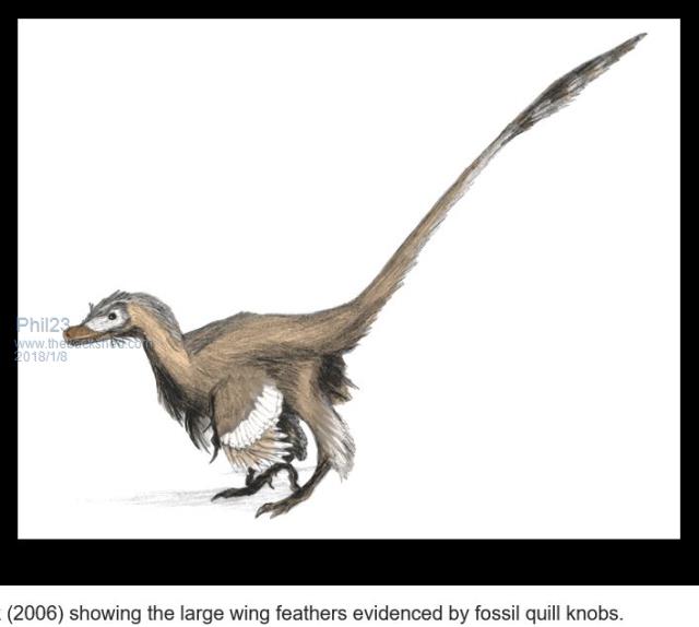 From Wiki.... Phil. |
||||
| redrok Senior Member Joined: 15/09/2014 Location: United StatesPosts: 209 |
Hi Grogster;I believe so. Although it would be prudent to have a 100K gate pulldown and a 1K series to the uMITE pin to protect from charge injection due to the MOSFET Miller capacitance. I like the RFD14N05. It is one of the standard parts in my junk box. I measured the RDSon at 64mohm @ 3.3V. The full on power dissipation would be only about 1 Watt. This part will have to be insulated from the plate. However, at 1.6W or even 1W, the package would not need a heatsink at all. Another part, TF2618L in a "Fullpack" insulated package and only 16mohm @ 3.3V. The full on power dissipation would be only about 0.25 Watts. And another, IRLI2203N in a "Fullpack" insulated package and only 8mohm @ 3.3V. The full on power dissipation would be only about 0.125 Watts. I've a listing of many parts on one of my web pages, see: Parts with which I've Used, Tested, or have an Interest. Lots of data here. The resistance of the rubber heater will change with temperature, that's inevitable, however, the absolute operating temperature of the wire is not much higher than ambient so the change of resistance is minimal. The first order approximation of resistance VS. temperature is: 25degC + 273degC = 298degK ambient 35degC + 273degC = 308degK the Bees ( 308degK - 298degK ) / 298degK * 3.2ohm = +0.11ohm resistance change 3.2ohm + 0.11ohm = 3.31ohm That's not a significant change in resistance. Have fun! redrok |
||||
| The Back Shed's forum code is written, and hosted, in Australia. | © JAQ Software 2026 |
