Notice. New forum software under development. It's going to miss a few functions and look a bit ugly for a while, but I'm working on it full time now as the old forum was too unstable. Couple days, all good. If you notice any issues, please contact me.
Azure Guru Joined: 09/11/2017 Location: AustraliaPosts: 446
Posted: 02:22am 22 Feb 2018
Copy link to clipboard
Print this post
@WW
My display looks similar to that photo with transistor in same position and it works fine with MM BP V2. Unless you are suggesting his one has developed a fault for some reason.
Transistor next to Touch Screen chip is warm when on full brightness.
No SD card inserted.
Lou
WhiteWizzard Guru Joined: 05/04/2013 Location: United KingdomPosts: 2991
Posted: 02:27am 22 Feb 2018
Copy link to clipboard
Print this post
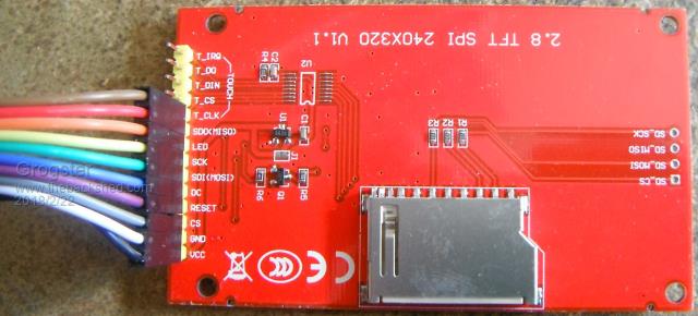
There are two common types of TFT 'out there' - one with a single transistor (as in this case), and the other type has two transistors.
The single transistor type TFT module seems to run warmer than the other type; and I believe this transistor drives the BackLight (I may be wrong - not got a TFT module next to me at moment to check). It could have a dry joint and I was going to recommend running an iron over the three pads. However, that said; the mention of a 'burnt smell' is worrying - so looking for the component most likely to have failed.
Unlikely to be any damage to the BP - but then why would the backlight suddenly fail
WhiteWizzard Guru Joined: 05/04/2013 Location: United KingdomPosts: 2991
Posted: 02:32am 22 Feb 2018
Copy link to clipboard
Print this post
@loup
Can you confirm that setting different values with PWM 2,1000,xx does indeed give a full swing in brightness from off (xx=0) to on (xx=100) - as well as variations such as 20,40,60,80
Just checked the board again using my best thermometer (lips!) and found the board is very warm at full brightness on the whole header side. I think this is where the backlight LEDs are so this is to be expected. Given that the PWM control works, I have to assume the PWM circuit is fine.
What irritates me is that this happened after a firmware load. Was working fine beforehand. I was trying to get back into a project I half finished 6 months ago and thought I would update the firmware! Murphy strikes again.
My guess is that the LCD is not driving the elements hard enough to allow enough light to shine through from the very bright backlighting.
Can confirm that cycling through the PWM 0,20,40,60,80,100 produces varying brightness from dark to full bright.
Lou
Azure Guru Joined: 09/11/2017 Location: AustraliaPosts: 446
Posted: 03:07am 22 Feb 2018
Copy link to clipboard
Print this post
I have to admit I am now confused.
From what you are saying: 1. The display works; 2. The PWM brightness control works; 3. The MM works (GUI test screen); 4. The Display gets warm on high brightness.
What is not working and where is the magic smoke trying to escape from (you should be able to smell if it came from a component on the backpack PCB or LCD panel PCB)?
Flashed using the pic32prog tool using on board microbridge.
Power source is PC USB.
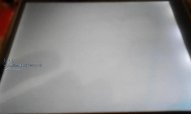
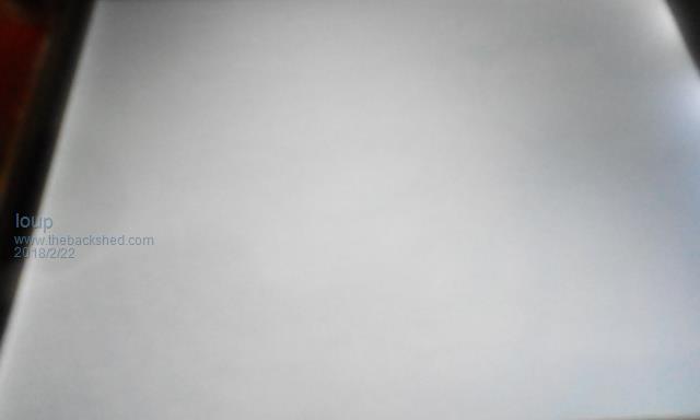
I do not think my camera will pick this up very well.
If I set brightness PWM to 5, I can angle the screen and just make out the colours from GUI TEST.
Anything above 10% PWM washes out the screen.
Lou
Azure Guru Joined: 09/11/2017 Location: AustraliaPosts: 446
Posted: 04:12am 22 Feb 2018
Copy link to clipboard
Print this post
I just checked the display I have with me at the moment, it is labelled the same "2.8 ... V1.1".
My one does have 2 transistors. I try and rummage through the others when I can get access tonight.
Grogster Admin Group Joined: 31/12/2012 Location: New ZealandPosts: 9975
Posted: 04:14am 22 Feb 2018
Copy link to clipboard
Print this post
Very odd.
Can we assume that this is your LCD display:
I would be wanting to DISCONNECT the LED line at this point, and then connect it directly to 5v via a resistor - 100 ohms will do for now.
Run your GUI TEST LCD DISPLAY command, and leave it running.
Change the value of the resistor on the LED line up and down, but don't go below about 33R or you might hurt the backlight. The more resistance you put in series with the LED line, the dimmer the display should get.
What this test does, is just remove the PWM drive from the LED line totally, so you can see what's going on there.
Personally, I suspect that the PWM output signal from the MM's BACKLIGHT command, is not working - although you say it does, so something does not make sense here....
I don't suppose you happen to have a logic analyser do you?
EDIT: My photo shows that U2 - the XPT2046 touch controller chip - is not installed, so you can ignore that fact. We're only interested in the LCD and it's backlight for the moment. Edited by Grogster 2018-02-23Smoke makes things work. When the smoke gets out, it stops!
Azure Guru Joined: 09/11/2017 Location: AustraliaPosts: 446
Posted: 05:09am 22 Feb 2018
Copy link to clipboard
Print this post
@Grogster
That is the same the LCD I have with me at the moment (working on location).
His panel only has 1 transistor.
I agree with your suggestions and also that something does not make sense.
Seems like an LCD Anode or GND connection issue.
What is confusing is that the LCD Backlight is a backlight to the LCD Display panel. So the brighter the LCD Backlight the brighter the display should be.
Grogster Admin Group Joined: 31/12/2012 Location: New ZealandPosts: 9975
Posted: 05:58am 22 Feb 2018
Copy link to clipboard
Print this post
Agreed.
The LED line is just the LED backlight, and it is common-ground, so if the backlight is so bright as to overwhelm the actual LCD display itself, it means that you most certainly DO have a very strong LED line drive(voltage and current) and that the ground is obviously good so no problems there. I would concentrate on a high-side problem rather then a grounding issue.
IS THERE SOMETHING THAT NEEDS SETTING on a fresh firmware on the Backpack? Perhaps something that configures or allows for either PWM control OR the variable-resistor trimmer backlight control?(but not both)
Watching this thread with much interest.Smoke makes things work. When the smoke gets out, it stops!
Bloody. I am having a "brown touch" day today. Everything I touch turns to poo. Pulled out my multimeter, turned it on, blinking screen. Changed the battery and magic smoke came out. Sheesh.