
|
|
Forum Index : Microcontroller and PC projects : How to learn RF remote codes?
| Author | Message | ||||
Grogster Admin Group Joined: 31/12/2012 Location: New ZealandPosts: 9982 |
@ PeterB - No, cos I still don't understand what you mean exactly.  I guess when you say 'Mono' you are talking about a monostable multi-vibrator, yes? I would not have the first idea as to how to proceed with discrete logic oscillator designs. I guess when you say 'Mono' you are talking about a monostable multi-vibrator, yes? I would not have the first idea as to how to proceed with discrete logic oscillator designs.  I might be completely missing something here, so feel free to explain in more detail. I might be completely missing something here, so feel free to explain in more detail.Smoke makes things work. When the smoke gets out, it stops! |
||||
| PeterB Guru Joined: 05/02/2015 Location: AustraliaPosts: 669 |
Sorry, I foget that not everybody grew up with TTL etc and that was after transistors and valves. So how about an interrupt set to trigger on the rising edge of your data and the actual interrupt reads the level on the pin after a delay of 0.4 ms. If the pin is HI it's a 1 If the pin is LO it's a 0 See, dead easy...............if it works. Peter |
||||
| Grogster Admin Group Joined: 31/12/2012 Location: New ZealandPosts: 9982 |
I will certainly look at that as an option. I have to work out how to hack the receiver module I have, to enable the squelch when there is no data present. Apparently this is done with a single resistor on one of the pins on the 470 chip(so says the PDF), so I am playing with that idea now. Smoke makes things work. When the smoke gets out, it stops! |
||||
TassyJim Guru Joined: 07/08/2011 Location: AustraliaPosts: 6541 |
Your method should work. Using a dedicated receiver chip will be the most robust. @Grogster, If you want more than 15, use two (or more) receivers on different addresses. Jim VK7JH MMedit |
||||
| Grogster Admin Group Joined: 31/12/2012 Location: New ZealandPosts: 9982 |
I just found this 1527 decoder module on AliExpress for one buck twenty..... It has data output pins, so I think I will get a couple of those to play with. It also has a VT output. The question is, can it decode more then ONE 1527 remote? EDIT: Here are the other 2272 decoder modules which are a whole one buck fifty. These ones have the 470 receiver IC, and the 2272 decoder in the one module. These ones I have used before, and they are wonderful. The 1527 module I THINK will only learn ONE remote code, and any of the four data bits can be accessed via it's output pins on the module. The 2272 module has the advantage that if you set the address the same in the transmitter and receiver, you can have up to 15 different transmitters on the same address. As Jim says, you could just use multiple addresses to get more transmitter codes, but each group of 15 would require a separate receiver/decoder module. At that price, not really a problem. Smoke makes things work. When the smoke gets out, it stops! |
||||
| Grogster Admin Group Joined: 31/12/2012 Location: New ZealandPosts: 9982 |
Change of plan. I really like a couple of the transmitter units, but they both use the 1527 encoder. Grrrrrr.....  I can see why. The 1527 is only an 8-pin SOIC, so it is small and easier to fit on a PCB. I can see why. The 1527 is only an 8-pin SOIC, so it is small and easier to fit on a PCB.I have decided to just make a receiver board seperate from the main system. The receiver board will have up to 20 of the 1527 learning decoder boards on it. This still seems a little messy to me, BUT having said that, each seperate decoder can be programmed for a new transmitter using it's on-board learn button, which makes life very simple for learning in new remotes, and totally avoids me having to write code to have the MM learn them. I will just use the VT lines(Valid Transmission) from each module as a signal to the MM controller. It's not ideal cos of all the receiver modules, but they are cheap and they take all the hard work out of the project, as I don't have to get the decoding working inside the MM if you catch my drift. I will probably replace the coil antenna with proper 433MHz helical ants, which I have plenty of. They would probably be a better match then the little coil they come with. So, I have ordered two of those decoder modules for now to play with this idea. You can buy 20 at once for US$18 on another listing. It is all about reducing my stress level trying to decode the 1527 data.  Smoke makes things work. When the smoke gets out, it stops! |
||||
| WhiteWizzard Guru Joined: 05/04/2013 Location: United KingdomPosts: 2991 |
Hi G, One thing to test is having many RXs in close proximity. With RF, strange things can happen to receivers when positioned close together. It was a common issue with RFID set ups - so am just highlighting it here. Hopefully it won't affect your concept - but do check it |
||||
| vegipete Guru Joined: 29/01/2013 Location: CanadaPosts: 1181 |
Ah, those logic analyzer plots look familiar. Indeed, I have a bunch of bits scattered on the desk in front of me related to just that. Years ago, we used Visonic transmitters and receivers in a product we sell. These used a 12 bit protocol: 8 bits for the address, 4 bits for the data. The length of the pulse determined whether a bit was 0 or 1. Then they stopped making the transmitters. We found a somewhat suitable replacement transmitter from China that our existing stock of receivers could understand and production continued. These new transmitters send 24 bits of data so the firmware had to be rewritten to understand both types of transmitter. All was well until our supply of receivers was consumed. I tried the cheap receivers that came with the transmitters but was stymied by the noise output when there was no transmission. The firmware worked without changes, but was slow to respond to signals because it was trying to decode the noise and needed more good signal to purge the old rubbish. I reverse engineered the original receiver enough to identify a squelch circuit with op amps to zero the output when the incoming radio strength was low. Hmmm. In the end, I went with a better quality receiver from Linx Technologies, part number RXM-315-LR. (They make a 433MHz version too, RXM-433-LR.) These cost a lot more but we need the quality. The nice part is the they output both the 'noisy' signal of the cheapies _and_ an RSSI, the radio signal strength. Turns out I could just feed to RSSI signal through a comparator then to the firmware and it worked fine. As far as decoding the received signal goes, my code runs on a PIC24 microcontroller (originally on a PIC16F627) and needs to receive the same code three times in a row before accepting the signal. The firmware measures pulse lengths to generate a sequence of zeros and ones and stores them in an array. A long zero indicates the end of a packet, at which point the number of received bits is counted. 12 and 24 bits results are decoded and acted upon. TL;DR During testing, I fed the wonky pulse train, as seen in Grogster's logic analyzer plot, straight into a UART receiver set for different baud rates. At some (random) baud rates, very consistent characters were output, an amazing case of garbage in good data out! However, this will only work if you can get a squelch circuit going. Otherwise, the UART will spit an unending steam of nonsense. Visit Vegipete's *Mite Library for cool programs. |
||||
| WhiteWizzard Guru Joined: 05/04/2013 Location: United KingdomPosts: 2991 |
 Excuse my ignorance - what does this mean? Excuse my ignorance - what does this mean? |
||||
| vegipete Guru Joined: 29/01/2013 Location: CanadaPosts: 1181 |
Too Long, Didn't Read Sort of a synopsis or summary of the previous wall of text. Or in this case, the only important part of what I blathered on about. ;-) Visit Vegipete's *Mite Library for cool programs. |
||||
| Grogster Admin Group Joined: 31/12/2012 Location: New ZealandPosts: 9982 |
I thought you were referring to the You Tube channel.  (just kidding!) (just kidding!)@ WW - Yes, that is something I was thinking about too. Multipule helicals in close proximity could in fact de-tune them all at once!  RF is quite a demanding mistress, with one way to get it right, and heaps of ways to get it wrong! I intend to line a couple of receivers up on a breadboard for a start. I will range test with ONE, then add the next one close by and range test again. If that works OK, I know it SHOULD be OK - famous last words in the electronic design area. If it does not.......then I will have to look at spacing them out more I guess. Smoke makes things work. When the smoke gets out, it stops! |
||||
| PeterB Guru Joined: 05/02/2015 Location: AustraliaPosts: 669 |
I still think this could be done with interrupts. INT 1 resets a counter to look for no noise or signal and when the counter reaches a set number INT 1 is turned off and INT 2 is turned on to decode the signal as I described earlier. After 24/48/72 bits have been received the system resets. The code was designed to be used in the very early days, transistors & wet string. Peter |
||||
| RonnS Senior Member Joined: 16/07/2015 Location: GermanyPosts: 123 |
I am also very interested in this project,it can be a useful addition to my "smart home" project .. this works very well for a long timeCurrently I decode everything with a logic analyzer and then send only by pressing a button to send. I use Peters "bitbang" command, The runtime of a basic command / processor speed has a great influence on the process it works with the PiCromite also maybe it helps a look at my "smarthome" thread to move forward Link Ron |
||||
Azure Guru Joined: 09/11/2017 Location: AustraliaPosts: 446 |
@Grogster Can you explain more about what you are trying to achieve. A bit more scope might clear up some questions and lead to helpful suggestions. I have questions like: Are the remotes keyfobs or something else; What sort of transmission for each unit (eg single or multiple buttons/switches); Are these units predetermined or can you choose them (therefor the transmit coding method); Are they permanently located or roaming units; Will they all be in proximity at once; What is the likelihood of multiple units tranmitting at the same time; Do you ideally want to code them (record their id) to one MM system; Do you ideally want that MM to react to transmissions from these systems; It should not be to hard to rework WW's timer test code to add a start sync detect to trigger any data capture if that will help. Are you able to post what the data signal looks like when there is just noise (no transmitter operating)? |
||||
| Grogster Admin Group Joined: 31/12/2012 Location: New ZealandPosts: 9982 |
I did have a little play with some more code on these receivers last night, but all I get back is non-sensical gibberish. There is no RELIABLE detection of the wanted bits from the white-noise in the background. Even if I try to detect the sync bit(long-low), the results were totally unusable. I have no doubt that PeterB could make it work - he seems to know this stuff! I did find some PICAXE code for an 08M2 running at 32MHz to decode the 1527 signal, but I cannot follow it, and it is a HUGE code just to be able to read those 24 bits. I can upload the BAS file here if anyone wants to see it. @ Azure: Remotes are SOS watches for emergency use.  Single button. Predetermined as per the 1527 chip. You CANNOT choose the code as sent, other then the last four bits of the 24-bit word.(not counting sync bit) Most of these either have all four data bits set at zero or one. The 20-bit transmitter address code bits are hard-coded from factory, and you cannot change them. Each physical chip has a different address code, so every chip sends a totally different code word. Roaming - fixed to arm of wearer. All in proximity of each other. Multiple units transmitting at same time - could happen, but generally not an issue. I was wanting the MM to be able to learn the code from each watch. Yes, then if the MM received a valid code that it had learned, it could respond. I did not take a screen-shot of the white noise, as it was just white noise and no logical pattern to it. I have now pulled everything to bits as this idea was not really working out. I can reconnect and sample some of the white noise if you want. Smoke makes things work. When the smoke gets out, it stops! |
||||
| PeterB Guru Joined: 05/02/2015 Location: AustraliaPosts: 669 |
G;Day again. This assumes that the noise is consistent. In your main program set up a counter to increment every 1 ms. call it COUNT. Connect your signal to pin A. Set up INTA. on pin A to fire on anything and have it reset COUNT. So now COUNT will never get above 1 or 2 when noise or signal is present. In INTA or the main program add an if statement, if COUNT > 5 stop INTA and start INTB. INTB on pin B is as described earlier. It is set to fire on the rising edge of your data and, 0.4 ms later, reads the level on pin B which also has the data connected. If pin B is HI it is a 1 If pin B is LO it is a 0 Keep count of the number of bits received. After 24/48/72 bits have been received, reset back to the beginning. The above does assume some things about the noise so there is an element of doubt. Good luck. Peter |
||||
| Grogster Admin Group Joined: 31/12/2012 Location: New ZealandPosts: 9982 |
Thanks Peter.  I will re-read your post until I understand it. Bit manipulation is something that is a total mystery to me.  I will upload my test code as I go from this point on, so people can see what I have and perhaps suggest changes. I will upload my test code as I go from this point on, so people can see what I have and perhaps suggest changes.I will reconnect the receiver, 170 MM and logic analyser later and try some more testing. I will take a screen-shot of the white-noise and upload. Smoke makes things work. When the smoke gets out, it stops! |
||||
| PeterB Guru Joined: 05/02/2015 Location: AustraliaPosts: 669 |
You can do it in 2 parts. Part 1, detect the long zero Part 2, decode If part 1 doesn't work there is no reason to do part 2 So set pin C LO if COUNT < 2 and HI if COUNT > 2 and compare with data. You may need to fiddle the numbers. Peter |
||||
| Grogster Admin Group Joined: 31/12/2012 Location: New ZealandPosts: 9982 |
This was my first attempt: 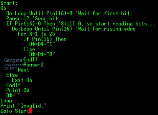 That was a total failure. Just with the white-noise it was outputting all kinds of code, none of which were valid ones. I was trying to detect the long-low and go from there, same as you suggest, but I was doing something wrong cos it did not work. I tried playing with the pause, but it made no difference. Admittedly, this was just my first attempt..... EDIT: Here is a screen-shot of the white-noise vs the data: 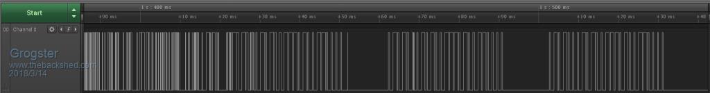 The white-noise is on the left, the sync and data words start from about the 50ms mark. This image shows TWO copies of the wanted data on the right, and white-noise on the left when the transmitter is off. EDIT: Forums have squished this image. If you want a clear GIF image, let me know and I will externally link to it. Smoke makes things work. When the smoke gets out, it stops! |
||||
| Azure Guru Joined: 09/11/2017 Location: AustraliaPosts: 446 |
@Grogster Edit: Sorry some of below might be redundant. Was trying to type this while working on a film set and by the time I pressed send there were more posts. Thanks for the extra info, it all makes more sense now and the constraints and considerations are clearer. Would still be great to see the white noise at least to see what levels it floats around. If you want to post the code happy to look at it and offer suggestions. Things that come to mind if we use edges or timing to build the bit sequence is that we should be able to detect a valid sync pulse and also timeout if it all takes to long. I will try and dig out my 433MHz bits and pieces on the weekend if that is not to late to offer testing/coding assistance. I think it is a good exercise to be able to build the bit stream that comes in after a sync pulse. It can then be processed to match whatever protocols are involved (so read 1527 encoder in this case). |
||||
| The Back Shed's forum code is written, and hosted, in Australia. | © JAQ Software 2026 |
