Notice. New forum software under development. It's going to miss a few functions and look a bit ugly for a while, but I'm working on it full time now as the old forum was too unstable. Couple days, all good. If you notice any issues, please contact me.
matherp Guru Joined: 11/12/2012 Location: United KingdomPosts: 11144
Posted: 08:01am 12 Mar 2018
Copy link to clipboard
Print this post
The oscillator is correct but in any case isn't used during ISCP.
If you have a spare PCB and want me to build one up to test send me a PM and I'll let you have my address
Also, on a spare board you can buzz out all the power and ISCP connections just to be sure.
Finally on your built board you can try soldering all the vias in the key connectionsEdited by matherp 2018-03-13
OA47 Guru Joined: 11/04/2012 Location: AustraliaPosts: 1044
Posted: 08:26am 12 Mar 2018
Copy link to clipboard
Print this post
@Matherp I am more than happy to send over a PCB for you. I will order some more chips and try the minimalist board install as you suggested.
BTW the current draw of 190mA you suggested puzzles me a bit as when I saw the 50mA draw on an un-programmed chip I thought that it was acceptable as I have noticed quite a jump on the 170 chips after they have been programmed. Are you suggesting that the chip/board should be drawing the 190mA before programming?
OA47
matherp Guru Joined: 11/12/2012 Location: United KingdomPosts: 11144
Posted: 08:29am 12 Mar 2018
Copy link to clipboard
Print this post
No: that is with MMBasic running and the chip at full clock rate. I just wanted you to check the current draw to see it was sensible relative to a fully running chip and it seems good
WhiteWizzard Guru Joined: 05/04/2013 Location: United KingdomPosts: 2962
Posted: 08:31am 12 Mar 2018
Copy link to clipboard
Print this post
@OA47,
Just to eliminate a faulty PICKIT3, are you able to program something else like a 28pinner?
OA47 Guru Joined: 11/04/2012 Location: AustraliaPosts: 1044
Posted: 08:46am 12 Mar 2018
Copy link to clipboard
Print this post
@WW I programmed a couple only days ago without any issues.
OA47
WhiteWizzard Guru Joined: 05/04/2013 Location: United KingdomPosts: 2962
Posted: 08:53am 12 Mar 2018
Copy link to clipboard
Print this post
OK - the last thing I can propose at this stage is to run some flux over the PIC pins and a 'wet tip'. I have had the odd PIC perform strange until I done this (even though visually it was fine)
Hopefully no design fault crept in between v1.1 and v1.2 (highly unlikely with Peter's track record )
OA47 Guru Joined: 11/04/2012 Location: AustraliaPosts: 1044
Posted: 07:02am 19 Mar 2018
Copy link to clipboard
Print this post
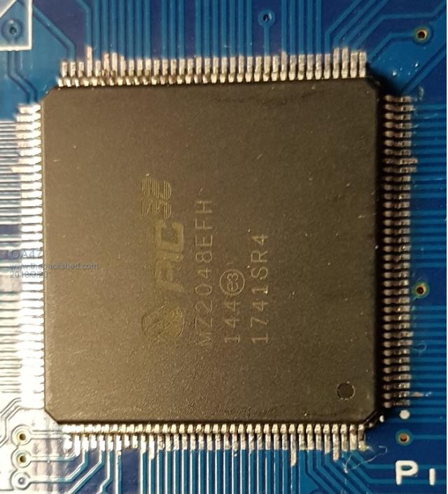
I received a shipment today of some new PIC32MZ2048EFH144-250 chips today so I thought I would have another crack at getting the PicKit3 to talk to the chip. I loaded the chip onto the PCB, added R18, L1 and a handful of 100n caps as mentioned by Matherp. Set up MPLAB to power the target PIC but still no bananas.
Is there a component that I still need to load to program the chip? OA47
BTW. I had successfully programmed a 170 an hour earlier with the same PicKit3Edited by OA47 2018-03-20
matherp Guru Joined: 11/12/2012 Location: United KingdomPosts: 11144
Posted: 07:58am 19 Mar 2018
Copy link to clipboard
Print this post
Shouldn't be anything else needed just to program. Did the PicKit load the new firmware when you changed from the 170 to the MZ?
OA47 Guru Joined: 11/04/2012 Location: AustraliaPosts: 1044
Posted: 08:17am 19 Mar 2018
Copy link to clipboard
Print this post
Yes
Connecting to MPLAB PICkit 3...
Currently loaded firmware on PICkit 3 Firmware Suite Version.....01.46.14 Firmware type..............PIC32MZ
Programmer to target power is enabled - VDD = 3.300000 volts. Unable to connect to the target device. Failed to get Device ID
matherp Guru Joined: 11/12/2012 Location: United KingdomPosts: 11144
Posted: 08:45am 19 Mar 2018
Copy link to clipboard
Print this post
There has to be a missing connection to one of the ICSP or power pins since we have eliminated everything else. To be pedantic check continuity across L1 - should be near 0 ohms or replace with 10ohm resistor. Your current measurements show there is no short VCC to GND so other than that I can only suggest you buzz out a blank PCB against the datasheet (rather than the schematic) to check every GND and VCC is connected and all the three ICSP connections are good from the header to the chip.
OA47 Guru Joined: 11/04/2012 Location: AustraliaPosts: 1044
Posted: 09:41am 19 Mar 2018
Copy link to clipboard
Print this post
Thanks Peter, I haven't done a current measurement on the second PCB, so I don't know the current draw. In my past experience the MPLAB software will advise if there is too much current flow when powering from the PicKit3.
I have < 0.3 ohm across L1
I did this on the first board and I will do it on the second and report back. OA47
matherp Guru Joined: 11/12/2012 Location: United KingdomPosts: 11144
Posted: 10:02am 19 Mar 2018
Copy link to clipboard
Print this post
Also check for short circuits on the ISCP pins
pin 1 (MSCP) 10K to VCC, capacitance to GND pin 4 open circuit to everything else pin 5 open circuit to everything else
Can you also post a picture of the chip on the PCB as close up as possibleEdited by matherp 2018-03-20
WhiteWizzard Guru Joined: 05/04/2013 Location: United KingdomPosts: 2962
Posted: 09:49pm 19 Mar 2018
Copy link to clipboard
Print this post
If you have a scanner AND an unpopulated PCB, could you scan both sides of the PCB and post the images here? The bigger the images are, the easier it will be to check track layout around the ICSP pins
OA47 Guru Joined: 11/04/2012 Location: AustraliaPosts: 1044
Posted: 10:26pm 19 Mar 2018
Copy link to clipboard
Print this post
@ Peter
I have checked continuity from the ISCP pins to the chip. I have checked continuity for each of the Vcc and Vdd connections as per page 9 of the Micromite Extreme Manual.
@ WW I probably have a couple of old scanners here, I have not used one for some many years, but I will be very surprised if they will be supported by the OS of my fleet of PC's. I will have a look and see what happens.
WhiteWizzard Guru Joined: 05/04/2013 Location: United KingdomPosts: 2962
Posted: 10:41pm 19 Mar 2018
Copy link to clipboard
Print this post
Sorry for asking this silly question - but I take it you are connecting the PickKit3 the correct way round? Pin 1 is nearer the I/O headers at the 'bottom' of the PCB - this needs to line up with the arrow (highlighting Pin 1) on the PickKit3.
Your photo above makes it look like there is minimal solder on the PIC pins. Have you tested continuity to the PIC Pin 'shoulders' rather than the PIC pads?
Run a wet iron on pins 37 and 38 (top right two pins in above photo).
Do you have a PIC16F1454/5 yet? I am now very curious if this method of programming fails too (i.e. via the excellent Pic32Prog)
WW Edited by WhiteWizzard 2018-03-21
WhiteWizzard Guru Joined: 05/04/2013 Location: United KingdomPosts: 2962
Posted: 10:48pm 19 Mar 2018
Copy link to clipboard
Print this post
Looking at your photos on Page 2 of this thread, Pins 37 & 38 appear to be shorted. It may just be a trick of the light reflecting, however, take a look under magnifier if you have one at hand.
From experience, the TQFP/LQFP PICs can easily suffer from 'bent' corner pins. This is mainly due to the PIC being dropped (even a very small distance) and it landing on a 'corner'.
That said, your photo above shows all pins nicely placed (albeit appearing with little solder on some of the pins).
EDIT: NO - some pins appear shorted on the EFH - look at the left edge; 11/12 pins up from bottom; and also 6/7 pins in from left on the top row
EDIT2 - This may just be light reflections - difficult to tell. However, from this angle, the pins look extremely close.
Can you take a close-up 'side-on' photo of all four sides?
Edited by WhiteWizzard 2018-03-21
OA47 Guru Joined: 11/04/2012 Location: AustraliaPosts: 1044
Posted: 10:53pm 19 Mar 2018
Copy link to clipboard
Print this post
@ WW I am connecting the PicKit3 pin1 to pin1.
All of the continuity testing was done to the chip leads not the pads.
Pin 37 and 38 are the programing pins and they are connected.
I haven't chased up followed up on the PIC16F1454's yet.
OA47
WhiteWizzard Guru Joined: 05/04/2013 Location: United KingdomPosts: 2962
Posted: 11:00pm 19 Mar 2018
Copy link to clipboard
Print this post
matherp Guru Joined: 11/12/2012 Location: United KingdomPosts: 11144
Posted: 11:33pm 19 Mar 2018
Copy link to clipboard
Print this post
From the picture you seem very short of solder on most pins. You will see connectivity when your probe is on the pin as it pushes it onto the PCB but it may then spring up after you remove the probe. Here is my scruffy but working version
FWIW, and I know WW swears by it, but I think flood soldering and then using wick to remove most is inviting this sort of issue. Don't know what technique you use.
OA47 Guru Joined: 11/04/2012 Location: AustraliaPosts: 1044
Posted: 01:41am 20 Mar 2018
Copy link to clipboard
Print this post
@Matherp This second attempt I did use WW's flood method unlike the first. I will re-do the pins with solder and see if that helps.
Just for clarification can you explain why the manual has two options for the PGD and PGC pins?
OA47
Page 2 of 3
Print this page
The Back Shed's forum code is written, and hosted, in Australia.


 )
)