
|
|
Forum Index : Microcontroller and PC projects : Output driving two LEDs
| Author | Message | ||||
| robert.rozee Guru Joined: 31/12/2012 Location: New ZealandPosts: 2528 |
no, the transistor can not be replaced with an opto-coupler. the BC547 and 2k7 resistor form a constant current sink, which is a key part of how the circuit work, whereas an opto-coupler is more akin to an on/off switch. i take it the 24 volt supply for the solenoids and the 3v3 supply for the micromite will share the same earth (0v) connection? if this is so, then there is not really any reason to use an opto-coupler. cheers, rob :-) |
||||
| Volhout Guru Joined: 05/03/2018 Location: NetherlandsPosts: 5931 |
Hi LouisG, Please evaluate attached proposal. Your original proposal (post #1) is implemented. Your question was: can I drive 2 LED's, answer: yes. Your total power consumption will increase with 128mA. Attached schematics should work. - don't forget the diode across the output (switch off of valves typically generates spikes). - check if you want 4 in one package opto couplers (TLP521-4) or individual ones(TLP521-1). In the Toshiba (TLP521) specification the isolation from IN to OUT is specified, but not the isolation between 2 channels in a package. If your use a common 24V power supply for all outputs the isolation between channels is not important. But if you have completely independent power supplies, it may. Regards, And please post a picture of the 32 channel driver circuit (and the application). 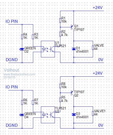 The LED can also be on the 24V side, this has benefit of showing you also that the 24V is present. 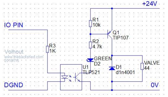 PicomiteVGA PETSCII ROBOTS |
||||
| LouisG Senior Member Joined: 19/03/2016 Location: AustraliaPosts: 130 |
Thanks Quazee and Rob. I'm presently overseas and will start breadboarding your (and my) ideas when I get back to Oz. I want galvanic isolation because there is a TIG welder continually used in the same premises as the Micromite. The welder generates a huge interference from its spark gap RF generator. The Micromite, a CG Microboard2, and connected to non-isolated outputs seems to be immune to this interference. However, when I was running out of pins I built an SPI driven output board for 32 circuits using four 595 shift registers. The board worked flawlessly until someone struck an arc with the TIG welder. Then all the outputs switched on! By disconnecting all the output field wiring the board worked as it should even with the welder operating. I surmised that the the field wiring was picking up the RF interference and causing havoc with 595s. To solve the problem I scrounged every available pin on the Micromite as outputs and now have zero pins spare. It works well but I'm soon going to need I/O pins again. Of course there's always the E100. However, the optoisolators are part of an attempt to make the output drivers bulletproof and suitable for any type of connection to the Micromite for this and future projects. Now you know. Incidentally, one weekend I crept into that workshop and played around with the culprit TIG machine. I found where the RF was apparently radiating from and tried an unorthodox makeshift modification on the machine, which eliminated the interference. It was never adopted. I'm still determined to improve the immunity of my Micromite control system. Louis |
||||
| Volhout Guru Joined: 05/03/2018 Location: NetherlandsPosts: 5931 |
EMC problems..... Metal box, grounded to 0V of the micromite. Powersupply internal (no external 3.3V or 5V wires). Success P.S. in Rob's design the source of the FET should connect to 24V. Don't forget the 1N4001 protection diode. PicomiteVGA PETSCII ROBOTS |
||||
| The Back Shed's forum code is written, and hosted, in Australia. | © JAQ Software 2026 |
