
|
|
Forum Index : Windmills : Star and Delta
| Author | Message | ||||
| woodchips Newbie Joined: 05/01/2009 Location: United KingdomPosts: 27 |
Sorry Niall, didn't mean to pick on you, just that you made the intelligent observation that was too good to pass by. As for axial flux alternators, a boring car journey raises some other questions. As I said before, the path of the magnetic flux seems to be one of three. Firstly the wanted one from the N pole on one disc to the S pole on the other disc through the coil. Secondly sideways from N to S poles adjacent on the same disc. Thirdly from all poles on both discs to the steel spacing drum on the outside and steel bearing housing on the inside. The shorter the path length for the flux, lower reluctance, the more of the total flux form a magnet will take that path, and here it has to be sideways. The second lowest reluctance will be from magnets to centre bearing and outside spacing drum. Only third will it cross the large gap from disc to disc. Immediate improvements can be had by increasing the reluctance of paths one and two. Space the magnets out so they are further apart, secondly replace the steel bearing housing and spacing drum with aluminium, non-magnetic. How much improvement? Trouble with increasing the magnet spacing is that the flux will simply go from the free pole around the magnet to the steel disc, so increasing the spacing beyond the thickness of the magnets might not do much. Replacing the spacer drum with aluminium should make a noticeable improvement. Let us analyse the alternator a little more closely. Where is the voltage generating magnetic flux coming from? There is the flux passing sideways between magnets, this will enclose the outer circular face windings of the coils, on both sides of the coil. With such close spacing I would guess not much would penetrate to the centre turns of the coil on the pitch circle diameter of the magnets. As the distance from the pitch circle increases outwards or decreases inwards then the distance between the magnets effectively increases. They are circular and curve away from each other. This will tend to lift the flux lines so they will penetrate a little higher into the coils. All this flux is essential circumferential, that is in the same direction as the rotation. This means that there will be minimal cutting of the flux by the coil windings and hence little voltage induced. Note that what voltage is induced is the same polarity on each side of the coil so it is opposed. So all that flux is wasted. There is the flux from magnets to outer steel spacer drum. This will be mostly from the outside diameters of the magnets to the spacer. The flux will be at an angle to the coils but will still result in some cutting and hence induce a voltage. This flux will only cut,say, 90 degrees on the outside of the coil and similarly of the bearing housing is also of steel. Problem here is that even though the flux is only cutting a small part of the coil, it will still induce a voltage, but that the voltages induced either side of the coil are opposing. You have the same pole hence same direction of flux and same direction of rotation so the same side, front or back, of the coil will be the same polarity. This is not good, it wastes energy and heats the coil. There is the flux that passes from one disc to the other. It would look like a column of flux passing from the N pole on one disc to the opposing S pole on the other disc. So each pair of magnets on one disc acts as a self contained magnetic circuit. From N pole across gap to S, through magnet to N to S of adjacent magnet, through magnet to N then across air gap to S, through magnet to N and through disc to S then through magnet back to N. This says that the discs do not need to be solid, they can be a spider with the two magnets on one leg. This could have important implications for cooling since what you now have is a crude fan inside the alternator stirring the air up. If the spacer drum is aluminium with external grooves then that would help cooling as well. It is this column of flux, cut by the coils, that induces the voltage output by the alternator. Or does it? There are two methods of inducing a voltage in a coil. The first is the classic Faraday method of relative movement between the wire and field. The second method is only mentioned in passing, but usually called the transformer effect because it relies on a change of flux threading through a coil. Here we have a coil with a changing amount of flux passing through it as it rotates across the magnets. So which method is used, are both methods used? Who cares? The answer must be that it will use both if it can and only one if it can't, it seems to be effectively impossible to split them apart. Is this something that can be exploited to increase the output, I don't know. The down side of the ironless alternator is that you are throwing enormous amounts of flux into it to overcome the reluctance in the long air paths. This flux will get everywhere and if there is something moving in it, then a voltage will be induced, take care with the bearing design if using ball or roller bearings. A possible improvement is to put pole shapers on the magnets. These are tapered iron with an angle of about 45 degrees with the top diameter about half the bottom, magnet diameter. These are well known to concentrate the flux, so by making the coils the inside diameter of the top of these shapers then the flux will pass across a much larger diameter of coil. Increase the wire diameter rather than number of turns. Brain frazzled. Bob |
||||
| GWatPE Senior Member Joined: 01/09/2006 Location: AustraliaPosts: 2127 |
Hi Bob, it is only once you make a prototype that you find that nearly all the flux ends up passing between the magnets, through the coils. I had expected loss of flux around the outside, through the iron ring that joins the rotors in my design. This does not seem to happen. I did many tests on my prototype to see if flux leaked out of the plates and jumped between around the outside, through the iron spacing ring. The magnetic flux lines tend to travel straight from one magnet to another across the gap where the coils are placed. I have just remeasured on my new AxFx alternator, and even with a 1mm airgap between the iron magnet disk and the joining ring, there is no measurable field present, even though there is still over 25mm gap between the magnets where the coils would go. I understand that as the emf is developed in the coils, and current flows, that this makes more of the flux lines pass through the hole in the centre of the coil, rather than through the wires. I do not believe the dynamics are well modelled with simulators. Gordon. PS it would seem that the flux still prefers to go the shortest distance, even if there is iron present. become more energy aware |
||||
oztules Guru Joined: 26/07/2007 Location: AustraliaPosts: 1686 |
Bob, Sorry I've been busy, so can't respond in as much depth as your observations require.... so I'll be brief. The flux behaves as I have stated. The geometry and the symmetry are responsible for the wave form... don't talk about it..... make one and show that I'm wrong. We both agree that Delta will suffer losses from circulating currents from either ...waveform (if a big departure from sine), and the harmonics developed from the diode hash, and the squaring of the wave by the battery bank, and I suspect from the back MMF fringing the fields once we get under higher power.... The trouble is it is nowhere near as great as you suspect. People switching from star to delta as the rpm increases, experience a large power increase. They would not bother otherwise .... Yes, slightly better results can be obtained by rectifying the phases, and the switching is slightly simpler, but most seem to feel delta is fine for this application. If you wish to think otherwise, then continue to think they are dills.... I admit, VHS won over Beta, and PC's won over Macs.... so popular is not always best, but obviously good enough for their purposes. Your analysis of the axial flux seems fanciful to me, but in truth some of it could be true if designed exceptionally poorly. Happily, you can deviate a bit from the rule of thumbs for these thing. If you stay inside these simple rules, you will avoid all of the negative things you have conjured up, and an excellent machine results.... the likes of which is very difficult to beat for high power/low rpms. Lets see if these can get your basic assumptions on track, instead of making them up. This is for the normal axial flux like Nialls and mine. Not to be confused with the 2 very swish ones from Gordon and Phil. Only two in existence like that.... thousands of the normal ones. 1. Make the inter magnet spacing at least the air-gap width, and if real estate permits, at least half a magnet width. (minimise leakage to non-existant) I prefer to use a larger disk and use about 3/4 magnet width.... more winding space is the main reason.. less R 
2. Make the coils hole similar to the magnet width. If real estate is scarce, encroach on the inner diameter up to 10% or so. (wave shaping) 3. If the disks are built, and a paper clip sticks to the back, you need thicker steel for the disks. (leakage) 4. The best airgap width is roughly 3/4 of the thickness of the magnet pair. ie if you have 1/2" thick magnets, then the ideal airgap is about 3/4" (best available winding window for least resistance) 5. There should be no attraction between plates proper. (you don't need Al spacers at the center to stop the plates shorting the fields. The plates will be neutral) As passing interest, most people use stainless all thread and nuts to space them apart... not because of leakage, but we all hate the bolts sticking to the magnets, and it allows for air-gap adjustment (to match the load to the blades). It is not used to stop shorting the flux... there is none there to short... so that was a baseless theory..... in a car alt with a permanent magnet replacing the field coil... a stainless shaft (non-magnetic) is very very desirable.... although it will work without it. 6. You should use the entire winding window if possible (once the turns are known, use biggest wire to fit.) Get R down to the minimum...best rule really, as it is a product of getting everything right. 7. Use a magnet to coil ratio of 4:3 for three phase in this single layer construction... simple geometry... a North pole will be over a single phase group. and will progress to the next phase group and then the next etc etc. like this: You will struggle to do better than this.. If you need to keep it smaller than the rules require (crowd the magnets), then your wave shape will be compromised, which means that Delta will be lossier.... but apparently no where near as much as you think. In reality, most of not all axials are Star. There are a few I know of in "jerry rig" (every coil... not group is independently rectified... 9 bridges etc) This is probably the best system from extensive testing.... yes better than star in some respects, and less prone to burnout if under magnet design. The obvious reason is the circulating current mitigation. As we are winding for our purposes, this is the obvious choice... we have a choice. If we are using pre-existing motors (eg induction conversions), then Delta is more likely used. If rewound, then Star. Delta is a perfectly good alternative if you can't use star. Independantly rectified is better, but not enough to get over excited about. The iron drag outweighs it where it is important (low power). .. So no I am not a proponent of Delta, but it is perfectly legitimate option in a lot of cases... not to be vilified... but building from scratch, star is the better option. Bad waveform: I think the rectifier losses will be higher, the more we deviate from a sine wave. (more harmonics from greater current shock at conduction (sq wave).... which is odd, as conduction starts at less than a volt, and cut in may be at 48v, so it is well turned on before having to support the current..... It would be helpful if you could explain that, as it is only a hunch I have... it may not be true, but I feel it is the sort of thing you would know... remember I'm not an engineer, and your welcome to look down on me for that, but others may wish to know as well. If your going to use Delta as your main configuration, then use rectified phase instead to address the circulating currents. If using for power (as in star delta switching), then it of little importance. Efficiency seems to be important only down low, where we are power poor. At higher rpm, we are power rich, and can afford too... in fact have too shed it copiously. Well Bob, you were loath to listen to the capacitor manufacturers right or wrong, and don't wish to listen to the axial flux manufacturers, but are happy to go on a tangent that does not represent the axials I am familiar with... You don't think we know how to test our machines, and don't believe the results..... You are of course free to expound your theory on the magnetics of axials, but when it clearly does not match the practical ...ie. built machines.....what's to say. I can't usefully work against that bias. I think that the theory behind your ideas is probably sound, so there must be something wrong with your basic assumptions, not the magnetic theories you have built it around. Your dissertation on axials does not match up with real world testing is all I can attest....If built as above, there will be precious little (I could not find) circulating currents at no load......... Think of this. Mine has no circulating currents below cut in that I have found. Nialls did. The only difference is the geometry and symmetry. The theory stays the same.......you explain it, it is your problem now. .........oztules PS. Smartdrives, the only reason, delta and parallel switching have such a big increase in power into the batteries, is the big impedance mismatch as the power goes up. By switching to Delta, we get 1/3 the resistance, and so Esq/R is better to drive the low impedance batteries.... likewise the parallel (R/2) It should be that star and delta develop the same power (and as Bob would point out,more losses for Delta) but there are other forces at play...... As you change the impedance match electrically (star to delta etc), the blade impedance to the wind changes, and the prop spins up and the TSR matching improves.... and lots more shaft power is available and at a higher RPM. Any loss via circulating currents is way over compensated by letting the prop develop much more power for the same wind, and the lower R taking advantage of that to drive the batteries, where star would just burn up... or run away in an iron cored version. So just switching from star to delta should not increase power.... but on a windmill charging batteries it sure as hell does..... driving a heating element it may be of no benefit, as that allows the voltage to rise with rpm, rather than clamping it, and you will probably need to add more as the wind picks up. It's called matching the load.... regardless of the alternator type and characteristics. Village idiot...or... just another hack out of his depth |
||||
niall1 Senior Member Joined: 20/11/2008 Location: IrelandPosts: 331 |
no worries Bob...you should see the girlfriend pick on me ... 
if only i could put a windmill in front of that..  .. .. niall |
||||
wind friend Newbie Joined: 01/05/2007 Location: AustraliaPosts: 39 |
Thanks Oz. So eloquently put. My bucket o bolts and coils that fell together in the form of a wind turbine is wired delta. The magnets aren�t perfectly placed and I�m sure the coils are out too. Of course there must be losses, but it works! This makes me happy. This was my first all metal project and I learnt much. Thanks Again. Hans. |
||||
| oztules Guru Joined: 26/07/2007 Location: AustraliaPosts: 1686 |
It has come to my attention that Hugh has placed this on his site which explains the 4:3 geometry of single layer 3ph designs. Hughs graphics This should help to visualise it perhaps. .........oztules Village idiot...or... just another hack out of his depth |
||||
herbnz Senior Member Joined: 18/02/2007 Location: New ZealandPosts: 258 |
Hi Oztules Notice comments re windings being in series star parallel delta. This is not the case. Its an time for a few facts on three phase. three phase is three separate supplies happening at different times (120 degs ) in star the instantaneous voltages if added are zero this allows the use of a common connection and saves copper in fact if balanced can operate with no return wire. there are three currents each flowing in its own winding and experiancing its own resistance (impedance )The current in the windings is the same as feeding to rectifiers. voltage between phases is 1.732 * phase volts. In delta its the fact the voltages as above add to zero allow us to connect end to end in what would be a short if batteries were connected this way. here the currents produced in each winding add together at the junction to give a line current 1.732 greater than phase current but phase voltage = line volts In the situation where we fix the line voltage by charging batteries, we can see delta will have less I squared R loss as each windinng is carrying 1/1.732 less current. heating will be less by the square of this reduction. We will have to however spin the turbine faster to get the same voltage. If this suits the wind strength alls good tho. However if the waveforms are distorted or not equal etc we will get circulating currents as talked about by others. We gain all the same as delta by bringing 6 wires out and rectifying separatly (jerry connection sort of) some seem to like rectifying remotly and will need to run more wires that carry less current. I have posted on another thread a test i have done to show how the higher frequencies and distorted waveforms cause quite a loss here. Another point is switching Jerry to star is much simplier only requiring 2 contacts. Bob I have stayed out of the therory versus practical discusion. The members I have noticed will eventually take on board what is said ie I notice not so much talk of pole saturation with load now, twisted poles are accepted etc . I can start to see I will soon have time to bench test the various combinations that at present I can see little verification for the conclusions presented. Herb |
||||
| wind friend Newbie Joined: 01/05/2007 Location: AustraliaPosts: 39 |
Why do we have multiple phases? Single phase is 64% efficient. No rotating magnetic field just a voltage rising and falling. The voltage falls to zero every 180 degrees. Three phase is 96% efficient. Now we have a rotating magnetic field with the voltage peaking with each phase in turn. (Google 3 phase wave form) At any point the voltage never falls to zero. When we rectify AC the bumps below the line become bumps above the line. The closer the bumps are together the more power we develop. Here in Aus and NZ electricity is generated 3 Phase in Star connection. The centre connection of the �Y� gives us our Neutral or zero volt point. This zero point is then connected directly to earth and forms part of our MEN (Multiple Earth Neutral) system. Here�s the interesting bit � the neutral is there to carry the out of balance current. Put simply, if there are three houses on a street each connected to a different phase and 2 of the houses are drawing 10 amps and the third is only drawing 5 there will be 5 amps flowing in the neutral. Why your neighbour might have power and you don�t in a black out. That�s also why the Neutral wire on the poles is thinner. At the power stations transformers change the generated electricity from star to delta, now we have 3 wires for transmission. Much less expensive. At your local sub station it goes back to star, now we have 4 wire transmission. Each phase and neutral. In your home switch board there is another MEN connection. Putting Earth and Neutral at the same potential (Voltage). From the Centre point of the Star connection to each phase we have 240 V AC, from each phase to any other phase we measure 415 V AC. For those with a mathematical mind � here goes (a squared times b squared) minus (2 times a times b times cos theta) = c squared. Gives you the hypotenuse of any triangle. Pythagoras� theorem. Draw a Y shape with each leg 240 mm long and 120 degrees apart and run a ruler over the ends of each line and if your drawing is accurate enough you should measure 415 mm. Back to wind turbines. There shouldn�t be any out of balance current if the magnets and coils are in the right place ish. This is the spark niall1 saw. Remember the Y drawing. If one of your lines was only 110 degrees and the other 130 degrees apart you would end up with an imbalance. If there is? Big deal. With research you will make a decision, star, delta, lower cutin speed, a number of turns for your coils, a magnet size � whatever. Build it � have fun, learn. We all want the most efficient wind turbine for our budget and skill, that�s why this forum exists. Hans. Phew.  |
||||
| oztules Guru Joined: 26/07/2007 Location: AustraliaPosts: 1686 |
Herb, What is the ratio of impedances of an axial flux unit with 1R phase coils in A: Star B: Delta I know load transformation conversions are 3:1 in favour of Delta....ie if R=1 for star, R needs to be 3 for a Delta equivalent... but? .........oztules Village idiot...or... just another hack out of his depth |
||||
| niall1 Senior Member Joined: 20/11/2008 Location: IrelandPosts: 331 |
mmmm... ok ...i think now we can now put my few watts of nomadic currents in delta safely down to pilot error...for battery charging its very little in the scheme of things ..as Hans said ...build it, have fun, and run it the way it suits your wind best.. a no brainer then i,m trying to follow the posts and learn something .....but its not easy keeping your eye on the ball...
maybe star v delta isnt the full story...but what either one is rectified into....... batterys seem robust...a sensitive grid tie inverter might ask a couple of questions who knows....... but lots to thing about niall |
||||
| herbnz Senior Member Joined: 18/02/2007 Location: New ZealandPosts: 258 |
Best to think in terms of each phase then derive the equivalent line impedance the rectifiers see. so if each phase has 1 ohm In star line will be vectorial sum ie 1.732 ohms. In delta line will be 1 ohm. In the case of charging batteries we have a situation both connections will be locked to one voltage (not a normal load ).The change is going to be in the turbine spinning faster in delta by in theory increasing by 1.732. This would in most cases increase power if the unit was near stall in star. Also as you have stated there will be less impedance in delta but best way to look at the effects of impedance is again go back to phase conditions. Lets look at say 10A line current and 1 ohm phase impedance In star this is a volt drop of 10 volts each phase the line volts will drop 17.32 volts. In delta to get 10a line current we only have 5.77a per phase a volt drop of 5.77 volts both phase and line. This is actually the 3 times gain you eluded to before. So there is gains in delta but does come back to getting the number turns right to take max advantage. Also I myself would not use delta due to other problems, all the same gains are there by switching to independantly rectifying with no problems. Herb |
||||
| oztules Guru Joined: 26/07/2007 Location: AustraliaPosts: 1686 |
Thanks Herb, we seem to be much closer in outlook than at first blush. I still think in terms of the effective driving impedance rather than the phase relationships as being primarily responsible... as the same thing happens in single phase (paralleling of coils and series coils behave in the same manner), and the same thing happens in star/jerry... which is then 3 single phase units... not connected in any way by phase per-say, but only three surges per rev, rather than a sine wave related phenomena. I think your bench tests will show you exactly what you expect to see.... if anyone can calculate the outcome of bench testing it is you. What they won't give you a clue to is how the alt will behave on the end of a prop in wind. The thing that will tell you will be the turns/volt and the effective coil resistance..... and taking into account armature reactance ie. the driving impedance if iron cored. The only way I know of measuring generated wind power is watts into the battery. This is terminal volts X current... or battery volts if you will times current..... or( Batt volts)sq/R The stator loss will be the (alt EMF- batt volts)sq/R .... R for air coil alts is close enough rather than trying to find Z We can use phaseless generation (commutator and brushes if necessary) and still prove that this is so..... so I don't think 3phase theory is necessary... or perhaps even useful to understand it. You will find with high R brush motors, you run into commutator losses that kill the output, but if you choose low R motors, you need to spin it faster, but get lots more out. With wind... it is all about matching. Good electrical design and poor wind match = 0 power. Crummy electrical design and good wind match = something.... not like a bench test at all. Like I have said a million times, my machine on a 24v battery is pathetic (maybe around 100W in decent wind and poor wind..... classic stall), 1-2kw@ 48v, 5kw@ 140v.... same everything except the load. That won't show on a bench test .... even a tiny bit. From a loaded prop to unloaded is is usually at least 2X the rpm (and if your standing near it... seems a lot lot more). Thats why star/delta switching works so well. When you choose to switch (stator loss near 50%) then the prop instantly raises TSR until it settles to the same kind (usually greater) of input power at a higher rpm..... but the change in loss in the stator is dramatic.... thats why it works with wind.... nothing else seems to be as to be as dynamic as the wind/prop relationship. If ..like when I went to 2 blades, you switch from star to delta, the change is more positive still... because it went from heavy stall (almost no power) to running efficiently (the prop that is).... lots of power to charge the car up. Delta's losses didn't bother me at all (yes they must have been there), the power increase is so significant in this case that I didn't bother to rectify each phase, I had more than enough..... and is tempory until I carve some more blades. Bench testing can only give me the unloaded volts/rpm. Thats all you need and the R of the stator in whatever config you are going to use. From that we work out the cut in we need, and then decide on blade size to suit what we are after. If your keen, you can get the power curve from bench testing, but this is only useful if you know how to carve a blade to suit it... otherwise they are just nice pretty graphs. No, you get volt/rpm , and prop size to work your cut in, and then use every possible geometry (coil size, shape inner size etc) you can to get the lowest R you can possibly get...... This doesn't match anything, but you now have options. The R is important for stator efficiency (read destructive heat) but a zero R stator cannot be used on a wind machine... it won't work. The blade will get up to cut in and stall. You will be in stall from here on. On a bench test you can keep inputting more drive, and watch the amps climb,... and maybe for Hydro too, but not wind. A zero R stator is great, as we can add lossy resistors externally and keep the heat there and not in the stator... yes Bob, we add resistive losses to get more power.... gobs more. But that's wind. It's the R that I need to concern myself with , but your insight into the world of 3 phase is insightful and very welcome by me at least. .........oztules Village idiot...or... just another hack out of his depth |
||||
| herbnz Senior Member Joined: 18/02/2007 Location: New ZealandPosts: 258 |
Hi This thread is about star delta changing to get low wind output then take a generater to delta for its designed output in higher winds we must no confuse people it is a comparision of star and delta. Here we have one winding with the turns to run at the desired wind and rpm in delta but are connecting in star for low wind performance. If we were designing for star running we would have lot less turns of heavier wire to take advantage of the star connection,it in fact would not generate in delta losses could easierly be as for a delta machine. Just thought it was necesary to clarify this in case some ppl think delta has less losses. All my bench testing is done into my battery bank I have no interest in other loads my driving motor is feeding of the bank also so no overcharging occurs. My own windmill is a FP so long since i looked at it but think is 80sp I can gain very little info by monitoring it all to fast for me. When I had a Tri star load dump on it it for the two years it was on it recorded average about 1KWH/day, it peaks out at 20a . Bench testing will least show rpm output and input power I must be capturing. I know my Hydro's are much easier to monitor in fact you can derive a lot info re generaters here with constant input power Herb |
||||
| oztules Guru Joined: 26/07/2007 Location: AustraliaPosts: 1686 |
Agreed Village idiot...or... just another hack out of his depth |
||||
| oztules Guru Joined: 26/07/2007 Location: AustraliaPosts: 1686 |
I have finally had the chance to rebuild the alternator of the axial flux. It had magnet cancer of which I will do a story soon. I have made some statements that flew in the face of other peoples sensible theories on why the axial flux should be riddled with harmonics and circulating currents, and be all but unuseable in Delta configurations. I mentioned the design parameters that I had used, and proposed as guidelines for others. So, rescuing the magnets gave me a chance to get those real world figures. For the magnet placement the rotor template looks like this.... to get some consistancy: 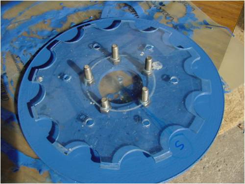
The populated rotor looks like this: 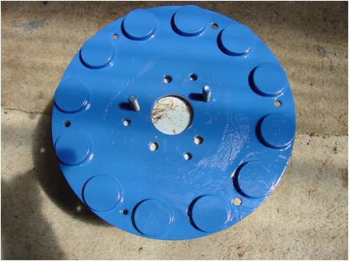
and the stator has round coils suiting the rotor... this and other parameters can be seen here: http://www.fieldlines.com/story/2008/8/18/83321/8140 The stator is wired in Delta for this test. A .5R resistor is in series with one delta leg. We measure the voltage across the resistor, and this will give us the AC circulating current. (I=E/R).... unloaded, and knowing the voltage across the resistor causing this current, we can get the power lost due to these circulating currents (ExI).... in this configuration. 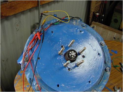
This picture gives us the ac phase voltage on the left, and the voltage across the .5R resistor. 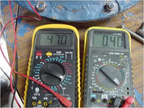
So phase voltage = 47v Current is the .4v across the 0R5 resistor. I=E/R =800 milliamps... this is hardly of significance in a .39R coil. The watts lost across the coil is only IsqR or .8x.8x.39 = .576W... thats all harmonics... everything all up... and it's around half a watt!.... a third of a volt at .8 of an amp... at twice cutin speed for the 36v electric car battery bank. This explains why I can't notice the torque required to drive the circulating currents.... it barely exists, and is less than the bearing drag and the wind resistance of the magnets whirring around, and also why it takes 12 seconds or more to slow down........and about the same with all phases open ended (no circ currents possible). So I reiterate, Delta is not the boogie man, it has circulating losses, but these can be small (and mostly overstated), even in a crappy design like mine, or larger in the classic Piggott design. (he has designed for star though).... I agree with Dinges on this aspect.... immaterial if it works better. It is infinitely more important to match the load, than worry about genny losses. If you don't get the load matched, you will have nothing to lose in the first place. If delta is matched better for your blade battery combo, then use it, if not I prefer star.... but I will use delta if it works better and currently do..... I'm using a lower voltage battery bank than I designed for... and only using 2 out of 3 blades (one broke) which does not help either on my 36v car... on my 48v mill.... it stalls the star combination at too low rpm..etc) Of course, there is another simple way to test this without even using a meter. I turned it by hand to get 47vac (about 66 Dc )in Delta.... thats near 300rpm, with only grasping the long bolts in the center....... leverage radius of about 2 inches. If I were using any real power,.. I aint superman....300 rpm by hand is spinning it like a demon..... if it used any significant power at all, this would not be possible, and the run down times would differ dramatically... they are all but the same. Theory is nice until you test it out sometimes... ...........oztules Village idiot...or... just another hack out of his depth |
||||
| niall1 Senior Member Joined: 20/11/2008 Location: IrelandPosts: 331 |
great to see definitive hands on tests done on this thread oz ....the results speak for themselves ...do you think the marginal current would be effected by any side effects caused by the rectifier ?....i,d kind of really like to blame it for a couple of watts on my alt ... ........but really it,s immaterial
looking forward to your thinking's about nickel plated magnet corrosion ....  ...now there's a real reason for locking up your daughter ........... ...now there's a real reason for locking up your daughter ........... niall |
||||
| oztules Guru Joined: 26/07/2007 Location: AustraliaPosts: 1686 |
Niall, The rectifier makes a complete hash of it. It must be the worst load to drive (rectifier into batteries) that we could find. It introduces a poor power factor by turning the sine wave... or reasonable facsimile thereof, into a squarish wave..... with all the harmonics that accompany it. It is such a lousy load, that using a petrol generator to charge batteries will derate the thing by perhaps half.... and it is obvious that things are not normal. It is terrible..... but... thats what we do. Whether your setup would have performed better in star than Delta, is unanswerable. It depends on the load matching. The thing that will have the least of all influences will be whether there are circulating currents present or not. It is this the electrical purists are missing. Getting the blades to extract the power from the passing air is step one.... and then building an alt to match.... it must match... never mind the efficiency... it must match the best you can get it to. The increase in usable power is enormous compared to stalled.....or not enough volts/turn and making nothing but turning anyway. If for the same blades, your delta stator didn't perform as well as your star stator, it will be more to do with your winding solution not matching the blades TSR and diameter, than anything to do with star or delta losses.... they would pale into insignificance.... poor matching is where we lose it. Think of this way, at 300 rpm, my delta impedance is .23R, at 47v thats 47x47/.23 watts possible in that stator... some 9000 watts..... and say 3 watts circ losses.... so what? In star, my stator is .7R... and voltage is up at 80vac. or 80x80/.7= about 9000W. I don't ever see that power into batteries (I've seen 5000 into an R load though), so the circ currents don't amount to a hill of beans really.... but the matching may be responsible for 6-7000 lost. (I haven't seen 3kw very often, and then I'm running away) and she's more than 300 rpm.... simple fear and terror ..........oztules Village idiot...or... just another hack out of his depth |
||||
| Dinges Senior Member Joined: 04/01/2008 Location: AlbaniaPosts: 510 |
Thanks for making those measurements, Oztules. Another case where 5 minutes spent measuring stuff ends years of misconceptions being repeated over and over. If you're game, would be interesting to see what would happen in the presence of rectifiers - does the current increase? More distortion? Might be an idea to use a scope over the resistor, instead of a DMM. Peter. |
||||
| oztules Guru Joined: 26/07/2007 Location: AustraliaPosts: 1686 |
Dinges, It's all too hard for me to work out how exactly to differentiate between the useful current and the circulating stuff. May need to measure input power, output power and see whats in between.... and it's on it's pole again now... albeit with 2 blades..... and in Delta.... and 36v..... non of which I designed it for... oh and it's furling backward...... Today I tested out Daveb's furling theory (procession and furling..... at this stage it is light years ahead of the results I have gotten with Hughs, and the Dans rotation/furling side technique. Will see when the wind picks up a bit... ...............oztules Village idiot...or... just another hack out of his depth |
||||
| herbnz Senior Member Joined: 18/02/2007 Location: New ZealandPosts: 258 |
Hi Oztules Its sometimes easier to believe than not believe expecially when there is a simple solution. Rather than Delta use three separate supplies to rectifiers (Jerry Connection sort of ) Advantages, no circuilating curents if they exist or not. real easy to change to star two contacts shorting out one end windings. less current in rectifiers and cables. Disadvantages need to bring 6 wires out only a problem if having rectifiers remote to gen, something I will not do at any rate. If using bridge rectifiers need 3 units rather than 2 you using round magnets and coils I would expect a pretty pure sinewave so at no load delta would be fine. Even F&P puts out not bad sinewave no load. Testing for circulating currents under load use two resistors one in delta one in line measure both compare ratio if less than 1.73 you have circuilating currents. As Dinges says a scope would be good particularly a double beam Herb |
||||
| The Back Shed's forum code is written, and hosted, in Australia. | © JAQ Software 2026 |
