
|
|
Forum Index : Microcontroller and PC projects : Picromite Aug 18
| Author | Message | ||||
GoodToGo! Senior Member Joined: 23/04/2017 Location: AustraliaPosts: 188 |
Hi Lewis, I think the SSD1963 connector orientation might be wrong if the connector is mounted on the other side of the board. Have a good look at Pin 1 as an example, especially compared to the Pi connector. With the board flipped, (ie. SSD1963 side up) is the connector on the left or right side? (Landscape more) Where is pin 1 on the display? Does it match up with pin 1 of the connector? Once you have the orientation correct, then you can wire it up. I suspect looking at your picture as is, that Pin 1 of the SSD1963 connector is actually in the Top left position, instead of top right. This would make all connections to the SSD1963 incorrect. Cheers, GTG!  ...... Don't worry mate, it'll be GoodToGo! |
||||
palcal Guru Joined: 12/10/2011 Location: AustraliaPosts: 2039 |
Lew, use your multimeter to make sure you have continuity from T_CS to pin 26 on the Picromite. The circuit as you have drawn it looks OK. "It is better to be ignorant and ask a stupid question than to be plain Stupid and not ask at all" |
||||
| GoodToGo! Senior Member Joined: 23/04/2017 Location: AustraliaPosts: 188 |
OK. Disregard my last post. I think I know what is going on, and it looks like what most people were trying to say with regard to the T-DIN/SPI-OUT and T-DO/SPI-OUT connections. Here is the SSD1963 connector. 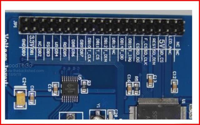 And here is my modified version of your PCB layout:- 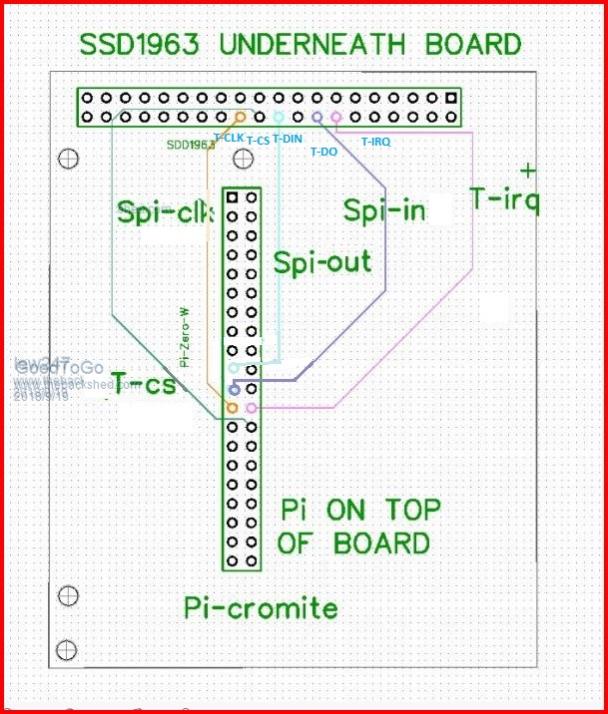 From your pin numbering, SSD1963 Pin 16 (T-DO) has to connect to Picromite Pin 21 (SPI-IN) NOT Pin 19 (SPI-OUT). Likewise SSD1963 Pin 20 (T-DIN) has to connect to Picromite Pin 19 (SPI-OUT) NOT Pin 21 (SPI-IN). At the moment your Touch (DIN/DOUT) SPI connections to the Picromite are reversed. Swap them around. Also note that your labelling of T-CS and SPI-CLK were swapped as well. Long story short:- Your SSD1963 pin 24 (T-CLK) Connects to Picromite Pin 23 Your SSD1963 pin 22 (T-CS) Connects to Picromite Pin 26 Your SSD1963 pin 20 (T-DIN) Connects to Picromite Pin 19 Your SSD1963 pin 16 (T-DO) Connects to Picromite Pin 21 Your SSD1963 pin 14 (T-IRQ) Connects to Picromite Pin 24 (I say 'Your SSD1963' because I think Pin 1 on the SSD1963 is actually the 'GND' pin in the top left corner? Anyone?) I hope the above helps......  Cheers, GTG! ...... Don't worry mate, it'll be GoodToGo! |
||||
TassyJim Guru Joined: 07/08/2011 Location: AustraliaPosts: 6538 |
I think he has the PiZero upside down. need to be flipped left to right. 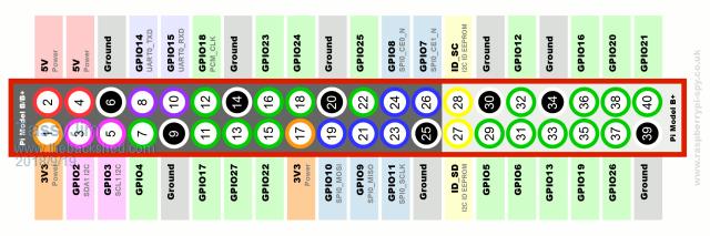 This should be the pins looking from above. Easily tested by using jumpers. Jim VK7JH MMedit |
||||
lew247 Guru Joined: 23/12/2015 Location: United KingdomPosts: 1709 |
Sorry TO make it clearer and EVERYTHING works perfectly other than when I try and calibrate the touch The top 2 calibration points work, once I touch the 3rd one I get "Hardware Failure" message I'm 98% the pins are correct - ?  |
||||
| matherp Guru Joined: 11/12/2012 Location: United KingdomPosts: 11513 |
Given this we know that T_IRQ is wired correctly. Check the Pi is all OK. First remove the display. For each of the 5 pins set them up as DIN. Connect wires at the display header between the pins and GND then the pins and 3.3V and check they read correctly ("PRINT PIN(n)") Connect SPI-OUT to SPI-IN at the display header then initialise SPI and execute "PRINT HEX$(SPI(&H55))" check it prints "55" Initialise SPI at a slow speed. Connect SPI-CLK to one of the COUNT inputs (e.g. SETPIN 12,CIN). Execute a single SPI transfer and check the count is incremented by 8 |
||||
| GoodToGo! Senior Member Joined: 23/04/2017 Location: AustraliaPosts: 188 |
You really need to be 100% sure. Pull both boards off and check for continuity and shorts between pins. One other thing, have you got the display SD card SPI pins connected to anything? I wonder if leaving them floating could cause issues? Cheers, GTG! ...... Don't worry mate, it'll be GoodToGo! |
||||
| lew247 Guru Joined: 23/12/2015 Location: United KingdomPosts: 1709 |
I found the problem eventually after checking about 10 times and 9 times I missed it T_DIN and T_DOUT were swapped so annoyed with myself |
||||
| lew247 Guru Joined: 23/12/2015 Location: United KingdomPosts: 1709 |
|
||||
Azure Guru Joined: 09/11/2017 Location: AustraliaPosts: 446 |
The important thing is you stuck at it and got it sorted out, well done. |
||||
| GoodToGo! Senior Member Joined: 23/04/2017 Location: AustraliaPosts: 188 |
Don't beat yourself up about it. As they say, s*!t happens. Joint effort by many people here that helped you out, not just me. Now have fun with it! Cheers, GTG! ...... Don't worry mate, it'll be GoodToGo! |
||||
| The Back Shed's forum code is written, and hosted, in Australia. | © JAQ Software 2026 |
