
|
|
Forum Index : Microcontroller and PC projects : LCD Panel Help Needed
| Author | Message | ||||
TassyJim Guru Joined: 07/08/2011 Location: AustraliaPosts: 6538 |
Maybe we should delay the desexing scheduled for next week and sell you a few offspring. That would pay for a lot of LCD panels. VK7JH MMedit |
||||
| panky Guru Joined: 02/10/2012 Location: AustraliaPosts: 1127 |
Relax Jim, all is good. Talk about trials and tribulations!!! Decided to wire wrap up a little interface board and after screwing up the wiring twice, finally got that correct. Still problematic - Oh woe, don't tell me I smoked the LCL with the dodgy wiring. Decided to put a scope onto the pins to check activity and found D5 had hardly any signal. Traced back to a dodgy solder joint on the PIC32 on pin 3. Fixed that, re-connected everything and all is up and running fine again. Whew!!!!!! Just goes to show that when Mr. Murphy has you down, he is not afraid to put the boot in. I guess the temp changes overnight affected the solder joint on the PIC and then I compounded that by suspecting and moving the rat's nest. All's well that ends well! 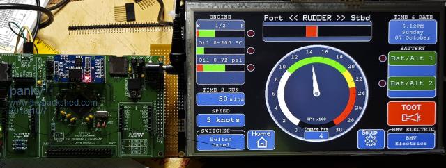 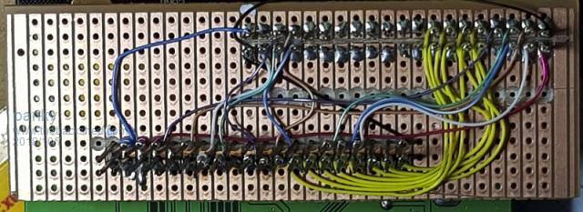 ... almost all of the Maximites, the MicromMites, the MM Extremes, the ArmMites, the PicoMite and loving it! |
||||
| WhiteWizzard Guru Joined: 05/04/2013 Location: United KingdomPosts: 2991 |
Hi Doug, Glad you fixed it all!  With that exact 9" panel you have there, what are the viewing angles like (horizontally and vertically)? From your photo it looks like a good quality frontal image. The 8" panels I use from BuyDisplay are really nice - I think mainly due to a good 'even' backlight illumination. I wanted to step up to the 9" panels but suspected that the image would not be quite as nice so it would be great to hear your opinion of the display quality. WW |
||||
| panky Guru Joined: 02/10/2012 Location: AustraliaPosts: 1127 |
WW, It looks bright and sharp at +/- 45 degrees horiz and vert. Horiz, I reckon it's still good out to 60 degrees or more. My vision is not so good now but I can read font 2 text at about 2 metres. This is with 5V LED power - it may be not so bright on 3V3 power - just don't know this. Comparitively, it seems at least as bright and sharp as my 7" if not better. At viewing distance of about half a metre, I still can't make out individual pixels (have to get really close to see them). panky ... almost all of the Maximites, the MicromMites, the MM Extremes, the ArmMites, the PicoMite and loving it! |
||||
| Bill7300 Senior Member Joined: 05/08/2014 Location: AustraliaPosts: 159 |
Interesting application panky, especially with that "Toot" button. What is it, a single engine tug? Bill Bill |
||||
| panky Guru Joined: 02/10/2012 Location: AustraliaPosts: 1127 |
Canal barge in France! ... almost all of the Maximites, the MicromMites, the MM Extremes, the ArmMites, the PicoMite and loving it! |
||||
Grogster Admin Group Joined: 31/12/2012 Location: New ZealandPosts: 9975 |
I have made a start on doing a PCB-based adaptor...... 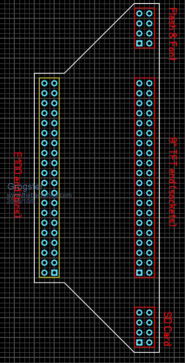 I will try to get one of the 9-inch TFT's in the next week or so, and by then I should have finished doing the adaptor. Smoke makes things work. When the smoke gets out, it stops! |
||||
| WhiteWizzard Guru Joined: 05/04/2013 Location: United KingdomPosts: 2991 |
Hi Grogs, By the way, this will be useable for the 8" TFT too! So maybe change the SilkScreen on the right-hand-side to '8"/9" TFT end....'  WW |
||||
| Grogster Admin Group Joined: 31/12/2012 Location: New ZealandPosts: 9975 |
Oh, sure, I am just playing at the moment.  The references in red are just to help me when I do the actual track routing. BTW, was this what you were thinking of? Smoke makes things work. When the smoke gets out, it stops! |
||||
| WhiteWizzard Guru Joined: 05/04/2013 Location: United KingdomPosts: 2991 |
The red text on the right - Yes! In case you thought this adapter was only applicable to the 9" - This 'little' PCB will be soooo useful.  |
||||
| Grogster Admin Group Joined: 31/12/2012 Location: New ZealandPosts: 9975 |
Oh, I love you too, WW....    The only think that really kept me away from using the EastRising displays, is their incompatible pin-out. But one thing that I really like about them, is that they guarantee supply - or so they say. This means you are probably better designing with these then anything else. Not that there seems to be any lack of the cheap displays on AliExpress or eBay.... Smoke makes things work. When the smoke gets out, it stops! |
||||
| panky Guru Joined: 02/10/2012 Location: AustraliaPosts: 1127 |
G, I haven't done anything about it myself yet but I would like to have a universal lcd interface board. It should include mounting holes for as many of the displays as possible as well as interfacing to as many boards as possible. Eg. Support ILI's 2.8",3.2", 4", SSD's 4.5", 5", 7", 8", 9" on Explore 100, matherp/circuit gizmos backpack 64, some of Peter's MZ boards and possibly Armmite. Big task but we all have to dream panky ... almost all of the Maximites, the MicromMites, the MM Extremes, the ArmMites, the PicoMite and loving it! |
||||
| lizby Guru Joined: 17/05/2016 Location: United StatesPosts: 3784 |
Great work. I also placed my order between working! and glitch!, so glad to see that it got sorted. panky--can you lay out your pin mapping? I'd like to try a version for the Explore64 board. +1 for Armmite layout as well. PicoMite, Armmite F4, SensorKits, MMBasic Hardware, Games, etc. on FOTS |
||||
| Grogster Admin Group Joined: 31/12/2012 Location: New ZealandPosts: 9975 |
@ panky - What did you do with TE on CON1 on the 9" display? They label it as 'Tearing Effect'. This does not correspond to any pin on the E100 that I can see, so I have left it floating at the moment, but if you used it, could you please say where it goes. Smoke makes things work. When the smoke gets out, it stops! |
||||
| Grogster Admin Group Joined: 31/12/2012 Location: New ZealandPosts: 9975 |
Here we are then: 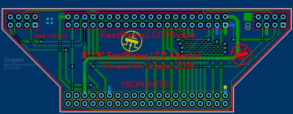 If anyone sees anything obviously wrong, let me know. The board still needs a little tweak here and there on it's size and the alignment of some of the text items, so ignore those for now. @ panky - I hope you don't think I have hijacked your idea or this thread. I did see you were going to make an adaptor, and then I saw your veroboard one, and I thought that must have been what you meant, whereas I meant a PCB version. I will discontinue posting on this thread about this board, if you would prefer. Smoke makes things work. When the smoke gets out, it stops! |
||||
| TassyJim Guru Joined: 07/08/2011 Location: AustraliaPosts: 6538 |
You don't seem to have data bits 8 - 15 connected. I think that some of Peter's firmware allows for a 16 bit interface on the 8inch. If they are not used, having them connected on the interface wouldn't matter. The flash chip needs to be on a separate SPI interface. I think that some of the mites use a dedicated SPI for touch and SD so it could not be accessed from Basic if not separate. For the mites that do use the same SPI, it would be no problem to link them but not through the 40 pin connector. You need access to the CS pin anyway. Jim VK7JH MMedit |
||||
| Grogster Admin Group Joined: 31/12/2012 Location: New ZealandPosts: 9975 |
No, I have not bothered with DB8-DB15, as it is not on the E100 pinout, which is what I am basing this board on. The board is only designed to allow you to connect an E100 to the EastRising TFT. There is no allowance(at the moment), to allow it to plug into anything other then the E100, as a direct plug-in adaptor so you can put an 8" or 9" LCD module from EastRising on the E100 - just as panky did. CS for the flash, touch and SD are remapped to the MM 40-pin header, so not sure what you mean by that last part. On an E100, the touch, SD card and flash are all on the same SPI bus from what I recall, each with it's own CS line - might be wrong, will double-check. I do hear you on keeping the touch and SD SPI separate, so I will make changes there, and let the host board link things together as it does now. This will mean that the SD card and Flash connections will be separated as you suggest. Smoke makes things work. When the smoke gets out, it stops! |
||||
Azure Guru Joined: 09/11/2017 Location: AustraliaPosts: 446 |
Just thought it might be worth putting the MM+ Exp100 pin numbers and mapped function on the silkscreen somewhere (I know you mentioned you were still working on the silkscreen). That would make it easy to know what display pin/function goes to what MM+ Exp100 pin down the track. |
||||
| TassyJim Guru Joined: 07/08/2011 Location: AustraliaPosts: 6538 |
On the Explore64 and 100, the SDcard and Touch both use SPI2. You could wire the flash to use SPI2 as well but having the pins separate would allow users to use SPI1 instead, making life a bit easier. SD and Touch are happy together because they are in the firmware. It's when you use Basic or a CFUNCTION to talk to the flash that timing might get tricky. Jim VK7JH MMedit |
||||
| matherp Guru Joined: 11/12/2012 Location: United KingdomPosts: 11514 |
Please wire them, please |
||||
| The Back Shed's forum code is written, and hosted, in Australia. | © JAQ Software 2026 |
