
|
|
Forum Index : Microcontroller and PC projects : Water Level meter - How to sleep mode
| Author | Message | ||||
Grogster Admin Group Joined: 31/12/2012 Location: New ZealandPosts: 9975 |
I got mine from Element-14 at the time: Link. 74c each in NZ money, and freight is free if you buy $50 or so worth of parts. I usually combine my orders so that when I make an order from Element-14, it is at least $50 so I can get the free courier. Otherwise, it is $15 I think. EDIT: Disco's link is a better price. I'd buy them from there, but you might not want 100 of them.  These MOSFET's have a maximum Vgs of 8v, so you can't connect the arrangement from the photo above to more then 8v or you will probably destroy the MOSFET. As the HC12 only needs 5v, they are perfect for that. Just don't go putting 12v on it like it shows in the diagram above! Smoke makes things work. When the smoke gets out, it stops! |
||||
Timbergetter Regular Member Joined: 08/10/2018 Location: AustraliaPosts: 57 |
Thanks disco4now. 100 units on its way now. That should keep me out of trouble for a while! Thanks Grogster for the Element-14 tip. |
||||
| Timbergetter Regular Member Joined: 08/10/2018 Location: AustraliaPosts: 57 |
I have now got hold of the 4 components suggested by Grogster and cobbled together a prototype power supply for testing / learning purposes, using the circuit I reposted in an earlier post above. I have observed the circuit switching as expected for trigger voltages from 2 to 5 volts and mosfet source voltages from 2 to 8 volts. I am considering supplying power to the device with three AAA batteries. If I am understanding things correctly the Atmega328P should continue to operate reliably with a supply voltage down to 3.7 volts. The HC-12 would be happy at 3.7 to 5 volts. The JSN-SR04T ultrasonic sensor is specified to be nominally 5 volts supplied. I have tested this sensor with reduced voltage supply and it appears to work down to and below 3.7 volts. An alternative might be four AAA batteries with measures to lose one volt or so to the three devices. What would the consensus be for operating the project off three AAA batteries? |
||||
| lizby Guru Joined: 17/05/2016 Location: United StatesPosts: 3784 |
I am looking to try this winter in an unattended location a similar setup with a picaxe, HC-12, and DS18B20, using 3-AAs, 4 rechargable AAs, and an 18650 at 3.7V to see which lasts longest. AAs will last much longer than AAAs. I plan to sleep for 10 minutes, take a temperature reading, and if changed, take the HC12 out of sleep mode (SET pin low), and send. In addition to the temperature, I will send a reading of the battery level times ten, which is easily achieved using the PICAXE with calibadc Data3 ' use below for M2, X2 Data3 = 2611 / Data3 ' 1.024 * 255 * 10 / calibADC value: V*10 PicoMite, Armmite F4, SensorKits, MMBasic Hardware, Games, etc. on FOTS |
||||
| Timbergetter Regular Member Joined: 08/10/2018 Location: AustraliaPosts: 57 |
This project is progressing nicely thanks to the help I’ve received on this forum. I do have one problem though that is currently blocking further progress with the ATMEGA328P. By disabling the Analog to Digital converter and the Brown Out Detection and then putting the 328P in to its Power-down mode, I am able to achieve a supply current of 5.8 microAmps. I can then reliably wake up the 328P using the on-chip Watch Dog Timer. The problem arises when I add the statement – SoftwareSerial myserial (2,3) – to my sketch code. The program runs as before, but when it enters the Sleep (Power-down) mode the 328P is now drawing about 750 microAmps rather than the 5.8 microAmps previously. I would have thought that putting the 328P in to Sleep mode would have switched off any overhead needed to support SoftwareSerial. I suppose I could delete the SoftwareSerial instance before going to Sleep mode, but I don’t know how to do that. Any thoughts on what might be happening here? |
||||
| ryanm Senior Member Joined: 25/09/2015 Location: AustraliaPosts: 203 |
Any reason you can't just use the hardware serial? |
||||
| Timbergetter Regular Member Joined: 08/10/2018 Location: AustraliaPosts: 57 |
I am using the HC-12 wireless module in this project so I thought that SoftwareSerial was the appropriate interface. |
||||
| ryanm Senior Member Joined: 25/09/2015 Location: AustraliaPosts: 203 |
Is your sensor serial interface as well? |
||||
| Timbergetter Regular Member Joined: 08/10/2018 Location: AustraliaPosts: 57 |
The sensor is the JSN-SR04 ultrasonic with trigger and echo signals. I am also using pins 2 and 3 on the 328P for serial interface to upload programs. I guess I come back to my question on why entering sleep mode does not switch off whatever resources the SoftwareSerial instance is consuming? |
||||
| JohnS Guru Joined: 18/11/2011 Location: United KingdomPosts: 4335 |
Just for a test, could you change to hardware serial and see if that fixes it? Otherwise you probably need to hunt around the software to figure what's happening. John |
||||
| Timbergetter Regular Member Joined: 08/10/2018 Location: AustraliaPosts: 57 |
  I thought I had ironed out the sleep mode issues while the project was in breadboard stage but as you can see the hardware has progressed a bit beyond that now. The thing is functioning as intended, that is: Wakes from sleep mode using on-chip WatchDog timer. Grogster MosFet is awakened which in turn switches on HC12 and Ultrasonics. Water level reading made and sent over the HC12. Shut down MosFet. Return to sleep mode. So far so good. The problem is that the sleep mode current of the entire device jumps from 6 µA to several hundred µA as soon as the SoftwareSerial instance is created. If the “SoftwareSerial mySerial (3, 4)” statement is added to the sketch the sleep current jumps to around 106 µA. Initially I had erroneously reversed the pin assignment in that statement and this caused the sleep current to jump to 760 µA, (and of course the device did not function then). If I entirely remove the HC12 from the main board the sleep current drops back to 6 µA (with the SoftwareSerial statement present). I would have thought that after entering sleep mode that the presence of a switched-off HC12 on any 328P pins should not have any significant effect on the current while in that sleep mode. I note that the Digital Pin 3 that I am using for RX can also be used as one of the two interrupts (INT1) on the 328P, but I am not initialising this pin as an interrupt. I am initialising INT0 which is pin 2. Could the split personality of Pin 3 be accounting for what I am seeing? I would have to rebuild the breadboard to put this to the test. Is there a way I can destruct the SoftwareSerial instance prior to going in to sleep mode? Could that work? |
||||
| ryanm Senior Member Joined: 25/09/2015 Location: AustraliaPosts: 203 |
Sounds like one of the software serial pins is being left high or floating and it's letting current leak into the radio. Try sending the software serial lines low with a digital write before entering sleep mode. |
||||
| Timbergetter Regular Member Joined: 08/10/2018 Location: AustraliaPosts: 57 |
Many thanks Ryanm. That worked absolutely. I am now back in the race for a battery powered water level meter.  |
||||
| Timbergetter Regular Member Joined: 08/10/2018 Location: AustraliaPosts: 57 |
My water level sensor is working as intended when the supply voltage is above about 4.55 v. The ATmega328P wakes from sleep mode sends DP5 high thereby switching on the MosFet which in turn switches on the ultrasonic sensor and the HC12 radio. After transmitting the reading the MosFet is switched off by sending DP5 low and then the ATmega328P is put into sleep mode for roughly 8 seconds (for testing sessions). When the supply voltage falls below 4.55 v the system works for 1 or 2 or even up to 6 sleep cycles, but then goes into a state where DP5 is stuck high and the MosFet is stuck on. The attached DSO trace is illustrating this situation for a supply voltage of 4.0 v. Channel 1 (yellow) cleanly goes high for 1 second and for two sleep cycles but on the third attempt becomes stuck high. Channel 2 (blue) shows the output of the MosFet which correspondingly goes on for 2 cycles but becomes stuck on after the third attempt. I do not understand the behaviour of the MosFet output trace which seems to indicate an oscillating ramp up to about 3.5 v ahead of DP5 going high. Any thoughts on what might be going on here would be most welcomed.  |
||||
| Timbergetter Regular Member Joined: 08/10/2018 Location: AustraliaPosts: 57 |
I have done 2 things that seems to have improved things somewhat: 1. Made the pull-down resistor for ATmega328P’s output pin D5 more aggressive by changing value from 10k to 4.7k. 2. Reduced the R7 resistance going from pin D5 to the base of Q10 from 1000 ohms to 470 ohms. (refer to Grogster’s suggested circuit on upper part of Page 2 of this thread) These two adjustments seem to allow the supply voltage to drop down to around 4.0 volts before the ATmega328P’s pin D5 hangs high. (It was 4.55 volts per my previous post). I was hoping to get it to continue operating down to around 3.7 volts to squeeze the best out of the 3 AA batteries, but at present the operation is unstable down there. I am observing something on the DSO traces that I don’t understand but I suspect it might be a clue as to what’s going on. The Atmega pin D5 goes high for 1 second to carry out the waking duties. However for about 1.5 seconds prior to that pin going high there is a succession of spikes at intervals of 68 mSecs. These spikes seem to give rise to an increasing voltage for Vout (the output of the MosFet) which climbs to about 2.6 volts before switching on properly to about Vsupply. The traces below are for a Supply of 4.0 volts. When the Supply is up at 5 volts I get a similar ramping effect but not as pronounced. (it persistes for only 0.9 seconds rather than 1.5 seconds). Does any of this make sense to anyone?  |
||||
| Timbergetter Regular Member Joined: 08/10/2018 Location: AustraliaPosts: 57 |
I have spent some time trying to reduce the voltage spikes and instability problems that are evident in the traces in my previous post. The only thing that has quietened down the voltage spikes, which I’m guessing are implicated in the stability problems, has been to introduce a capacitor at C7 on the attached schematic sketch. It seems to me to be a bit heavy handed to be strapping a 470 µF capacitor across the digital pin Output (DP5) however it has produced a desired effect in both reducing spikes and producing stability in operation. The device has now been working without any lock-ups for several days now, even with supply voltages down to 3.7 volts. The current during sleep mode is now down to 6 µA, which will be great for battery operation. I do suspect that the 470 µF solution is probably not desirable and may be just masking a continuing underlying problem. I would be grateful if anyone could look at my schematic and see if anything stands out as silly. The DSO traces now show the absence of voltage spikes on DP5, although there is a brief and low intermediate step before DP5 goes fully high. The undulations on the MosFet output voltage are still there, though maybe not as severe. 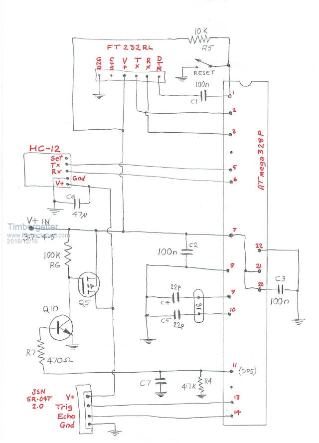 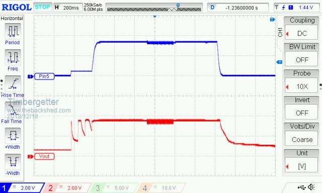 /* Sender-a1 ++++++++++ The BackShed Water Level Meter ++++++++ Incorporating suggestions from many BackShed Contributers Avoid using NewPing Library Introduce Sleep Function Use direct register management in lieu of any sleep library */ #define RX_PIN 3 #define TX_PIN 4 #define LOW_POWER_PIN 5 #define TRIGGER 7 #define ECHO 8 #define TooLong 15000 #include <SoftwareSerial.h> //int max_distance = 250; //int min_distance = 0; //int duration; int min_time = 1130; SoftwareSerial mySerial(RX_PIN, TX_PIN); void setup() { Serial.begin(1200); mySerial.begin(1200); pinMode(LOW_POWER_PIN, OUTPUT); pinMode(TRIGGER, OUTPUT); pinMode(ECHO, INPUT); // The attachInterrupt is only required if there is need to force wake status. //attachInterrupt(0, digitalInterrupt, FALLING); //interrupt for waking up // Setup Watchdog Timer WDTCSR = (24); WDTCSR = (33); // 8 Seconds sleep WDTCSR |= (1<<6); // Disable ADC ADCSRA &= ~(1 << 7); // Enable SLEEP SMCR |= (1 << 2); // power down mode SMCR |= 1; // enable sleep } void loop() { //delay(2000); // B digitalWrite(LOW_POWER_PIN, HIGH); // Power up the MOSFET // as per Grogster delay(500); int count = 0; unsigned long StartTime = millis(); unsigned long ElapsedTime; mySerial.println("S"); do{ long int duration = aping(); // Do the depth Sounding if(duration>0){ mySerial.println(duration); delay(500); count++; unsigned long CurrentTime = millis(); ElapsedTime = CurrentTime - StartTime; } } while(count != 10 && ElapsedTime < TooLong); mySerial.println("E"); // Close down power digitalWrite(LOW_POWER_PIN, LOW); // Power Down MOSFET delay(500); // May need to increase if no sleep // Stop current leakage from floating pins in to HC12 // as per ryanm digitalWrite(RX_PIN, LOW); digitalWrite(TX_PIN, LOW); delay(150); // May need to increase if sleep truncated // Put 328P to sleep sleepLoop(1); //delay(8000); //delay(2000); // A } long int aping(){ digitalWrite(TRIGGER, LOW); delayMicroseconds(2); digitalWrite(TRIGGER, HIGH); delayMicroseconds(10); digitalWrite(TRIGGER, LOW); long int xx = pulseIn(ECHO, HIGH); if(xx > min_time){ return xx; } else { //Serial.println("Too Close"); } } void sleepLoop(int loopNum){ // as per Keith Darrah // Sleep duration = 8 * loopNum seconds for(int i=0; i<loopNum; i++){ // BOD Disable MCUCR |= (3 << 5); MCUCR = (MCUCR & ~(1 << 5)) | (1 << 6); __asm__ __volatile__("sleep"); // go to sleep } } //void digitalInterrupt() { //support digital input interrupt //} ISR(WDT_vect){ // support watchdog timer } |
||||
| Turbo46 Guru Joined: 24/12/2017 Location: AustraliaPosts: 1693 |
Hi Timbergetter, I don't know if it helps but your arrangement of driving the transistor Q10 seems a bit odd. You may have your reason for it, but Q10 has a collector resistor of 100k and you are driving it with 470R? I would have thought 470k would be nearer the mark, even then the transistor would only need a gain of 5. Maybe 100k to be sure with another 100k from the base to ground may be more appropriate. The 100k to ground will help ensure that the transistor does turn off fully. I'd suggest that you try that without the capacitor. The 470uF capacitor is effectively shorting the output for a while and I agree that it is not a good thing. Bill Keep safe. Live long and prosper. |
||||
| Timbergetter Regular Member Joined: 08/10/2018 Location: AustraliaPosts: 57 |
Many thanks Bill for your observation and suggestion. I initially used a 1K resistor for R7 to be consistent with the schematic near top of Page 2 of this thread. At one point in my investigation I thought I observed an improvement by reducing its value. That’s the extent of my design basis. I’ll certainly give your suggestion a try-out shortly and report back. |
||||
| Turbo46 Guru Joined: 24/12/2017 Location: AustraliaPosts: 1693 |
Hi again Timbergetter, I confess that I have not been following this post. Arduinos and C are not my thing but the circuit caught my attention. I have read the whole post now. In addition to my previous suggestion, if the unexplained pulses are still there you could try a 100nF capacitor from the transistor's base to ground to filter them out. One could also be handy across the power supplies to the ultrasonic detector and the HC-12 as well - also try your 470uF capacitor across the incoming supply. Good Luck Bill Keep safe. Live long and prosper. |
||||
| Timbergetter Regular Member Joined: 08/10/2018 Location: AustraliaPosts: 57 |
I have made the first changes you suggested and the pulses were no longer evident with supply voltages above 4.0 volts. When supply voltage is reduced below 3.8 volts the pulses on output pin PD5 reappear. I set it running with a 3.7 volt supply last night and it did seem to be stable (albeit with pulses) for 30 minutes, but when I checked this morning the device had hung with PD5 stuck high and the MosFet stuck on. Do you have an idea where these pulses might originate. They are very regular at either 14.7 Hz or 13.9 Hz? I’ll try the 100 nF on the transistor’s base and see how that goes. |
||||
| The Back Shed's forum code is written, and hosted, in Australia. | © JAQ Software 2026 |
