
|
|
Forum Index : Microcontroller and PC projects : Enclosure with charging contacts...
| Author | Message | ||||
| Phil23 Guru Joined: 27/03/2016 Location: AustraliaPosts: 1667 |
Would you be able to put up a link to the items. I've got 3 coils here; think maybe intended in add-ins for a Galaxy S3, but can't get power from them; presume some signal is required on the third connection which is not straight forward. Looking for a more generic receiver. |
||||
| CaptainBoing Guru Joined: 07/09/2016 Location: United KingdomPosts: 2171 |
not silly - no-one born knowing all the answers and as you say; better to ask I think the pad is a magnetic screen... that was my reasoning anyway, seeing as it definitely doesn't work if I put it between the two coils and it is all cracked up (as if it were made of glass) but is ferrite looking... that's my story and i'm sticking to it until someone suggests something else.  |
||||
| PeterB Guru Joined: 05/02/2015 Location: AustraliaPosts: 669 |
Good morning palcal et al It is all explained in the data sheet for VISHAY IWAS-4832FF-50 You young blokes never listen  Peter |
||||
Grogster Admin Group Joined: 31/12/2012 Location: New ZealandPosts: 9975 |
Seems my guess was correct - it is a shield to protect the inductive coupling used in the wireless charging concept, from affecting nearby electronics. 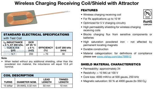 This one also has an 'Attractor' - a little bit of iron in the middle of the coil to help the coupling. Therefore, I expect the little black pad things go on top of the coil, with the coil sitting on the charger base, to stop any radiated magnetic field perhaps annoying nearby electronics. That would seem to be the situation. EDIT: "You young blokes never listen." - sometimes we need a prod from the older wiser members!  Smoke makes things work. When the smoke gets out, it stops! |
||||
| PeterB Guru Joined: 05/02/2015 Location: AustraliaPosts: 669 |
Good morning Grogster. You can leave out the wiser but thanks anyway. I tend to think of this as a 2D loop stick Peter |
||||
palcal Guru Joined: 12/10/2011 Location: AustraliaPosts: 2039 |
@ PeterB thanks for the younger bit but I'm pushing 76. "It is better to be ignorant and ask a stupid question than to be plain Stupid and not ask at all" |
||||
| PeterB Guru Joined: 05/02/2015 Location: AustraliaPosts: 669 |
palcal Only 76................. I'm pushing 82 so you can call me sir or Mr. in future. But at least I'm not pushing up daisies. I hope all the above solves your problem. Peter |
||||
| palcal Guru Joined: 12/10/2011 Location: AustraliaPosts: 2039 |
Yes all clear now thanks. @Phil23 This is the receiver here and the pad here "It is better to be ignorant and ask a stupid question than to be plain Stupid and not ask at all" |
||||
| Grogster Admin Group Joined: 31/12/2012 Location: New ZealandPosts: 9975 |
The little shields DO make a big difference to the charging current. Without it, charger current is 230mA or so, with the little shield placed on top of the charging coil - which is on the charger pad - the current jumps up to around 520mA or so. This is using a 5v @ 2A USB plug-pack/wall-wart thing. I might try a 10W charger, as the one I have is 5W, so a more grunty one should be able to charge faster, yes? Smoke makes things work. When the smoke gets out, it stops! |
||||
| JohnS Guru Joined: 18/11/2011 Location: United KingdomPosts: 4335 |
Vaguely in defence... I looked that device up but couldn't quickly find - or understand - the relevant information :( Thanks, though! John |
||||
| PeterB Guru Joined: 05/02/2015 Location: AustraliaPosts: 669 |
G'Day JohnS palcal & grogster opened their eagerly awaited new toys and were mystified when a strange lump of an unknown stuff fell out. The data sheet gives enough information to indicate what it is all about. It is possible my humor does not work well in other countries. If so, sorry about that. In fact, I'm not sure it works very well in Oz but as an Electronic Engineer I worked with Mechanical. Engineers. & Scientists and those still alive still talk to me and we did have a lot of fun. Peter |
||||
| CaptainBoing Guru Joined: 07/09/2016 Location: United KingdomPosts: 2171 |
dammit why did I stop my testing where I did? Once I had determined the "blocking" effects of the pad, I stopped thinking about stuff... must be getting senile!  Your measurement without tallies fairly spot-on with my own - although it was difficult to determine precisely as my ammeter has a 200mA range and the next is 20A, so it was off-scale on the lower and not registering on the upper. The current setting on the electronic load is only ever an approximation and it was complaining on the lowest setting of 200mA... so I had a meter that was saying it was above, and a load that was saying it was below... that's a ball-park figure if ever I saw one!  |
||||
| JohnS Guru Joined: 18/11/2011 Location: United KingdomPosts: 4335 |
PeterB - no need at all for apologies. I should've tried harder, perhaps, but software is my thing, really. CB - If it raises the current is that because more power is being usefully transferred across? John |
||||
| CaptainBoing Guru Joined: 07/09/2016 Location: United KingdomPosts: 2171 |
Yeah I guess so - the magnetic field is the only energy available so i 'spose it has to be that. Like I said, I am not into magnetics much - some of the stuff on here about rewinding inductors and transformers... I get the basic principal of it but it is still a dark art to me. |
||||
| CaptainBoing Guru Joined: 07/09/2016 Location: United KingdomPosts: 2171 |
OK, so I had an hour or two to potter... I made a vid here that shows my findings regarding these banggood wireless charger kits/modules. I have to say, that the little "ferrite" sticker seems to make things worse. And beware the voltage collapse as you start to draw current from them. I think to be on the safe side, you need to limit your current expectations to about 500-600mA, above this they start to behave quite oddly with no clean o/c shutdown (and it gets hot). Even with a moderate load (200mA) there was about a volt of noise - 20%! It needs some good Smoothing & filtering. enjoy |
||||
| PeterB Guru Joined: 05/02/2015 Location: AustraliaPosts: 669 |
Good morning CB I think your "little ferrite sticker" is probably meant as extra shielding between the receive coil and other electronics. Looking at the waveform does indicate a lot of noise. Good luck  Peter |
||||
| Boppa Guru Joined: 08/11/2016 Location: AustraliaPosts: 816 |
I'm not sure if these ones suffer the same issue, but quite a few 3d printers/makers have found these wireless chargers can get hot enough to melt their printed cases Not saying these particular ones can, but something for people playing with them to be aware of |
||||
| PeterB Guru Joined: 05/02/2015 Location: AustraliaPosts: 669 |
G'Day Boppa et al The upside of that is there are people out there who are 3D printing cases for these things. Grogster, CB etc have another avenue. It goes on & on & on......... Peter |
||||
| CaptainBoing Guru Joined: 07/09/2016 Location: United KingdomPosts: 2171 |
@PeterB I agree with you - it is effective enough as a shield to stop the inductive coupling completely - i.e. when placed between the two coils, no (appreciable) energy transfer occurs, so yep I think you are spot on. Just didn't expect it to "steal" 20% of the transferred energy when simply close to it. @Boppa The "transmitter" doesn't get very warm - it is discernible but nothing to worry about that I saw. The "receiver" on the other hand; the board was uncomfortable to touch at *all* levels. It seemed that once it had gone on the juice there is a considerable amount of heat generated. I couldn't really equate this with current draw, it seemed just as bad at 200mA as at 600. When I say hot, it was too much for a finger over time but not enough to cause rapid withdrawal accompanied by swearing, so probably abound 60-70C. From this observations there isn't enough heat to melt PLA (160+C, I have touched an active extruder nozzle and that does produce swearing) but I reckon it would cause a relaxing and visible change in any plastic in contact with it. regards h |
||||
| Boppa Guru Joined: 08/11/2016 Location: AustraliaPosts: 816 |
Some have reported measured temps as high as 80C, which wont cause a fire, but has caused 3d printed cases to visibly 'droop' under the combination of weight and temperature I would be worried more about a deforming case causing things to move together enough to cause a short or whatever Was just a 'headsup' for those playing with them |
||||
| The Back Shed's forum code is written, and hosted, in Australia. | © JAQ Software 2026 |
