
|
|
Forum Index : Microcontroller and PC projects : MICROMITE EXPLORE 64 BOOTLOADER
| Author | Message | ||||
disco4now Guru Joined: 18/12/2014 Location: AustraliaPosts: 1127 |
The test I suggested with ? PIXEL(100,100) will only work if the optional RD pin is connected, soit failing does not necessarily mean display is not working. You can try a slower speed to reduce effect of any noise in the wiring to the LCDPANEL. Page 15 of the manual mentions this. CPU 40 F4 H7FotSF4xGT |
||||
| arvindk Newbie Joined: 31/10/2011 Location: AustraliaPosts: 21 |
Thanks disco4now. As per the manuals, RD pin is permanently connected to 3,3v, i suppose to have it always "Read". ? pixel(100,100) result is 'error: pixel is not defined". I took it to meen that TOUCH option is not on. option touch 18, 21 (T_CS and T_IRQ resp.) Result"not calibrated", "gui calibrate" asks for calibration points, whish cannot work on dead screen. Not only that but it goes into a continuous loop till you type "option touch disable". you have helped so much. I think thr lcd is dead. I took all possible care, but as I said, when connecting 1983_PWM to its nominated spot, I did cause visible over-heating. Cann this have been enough to kill the lcdpanel? BTW all 3 connectting points were unsolders when the lcd was received. -Not shorted to LED_! as asked to removed the short there. I am not game to try removing 1963_PWM and install LED_! connection innstead. My eyesight is very poor. ALL in all I think I will just give up.At no stage did I see even a flicker from the backlight. I was only wanting to complete the project, because it was lying waste. I really appreciate help from you and the other friends. I am goimg to give away all my electronics stuff. ak |
||||
| Mixtel90 Guru Joined: 05/10/2019 Location: United KingdomPosts: 8911 |
Please don't feel disheartened :( I know it can be a struggle, but there are many ways to carry on playing in this hobby. :) My own eyesight isn't all that good, but a reasonable pair of illuminated magnifying glasses have worked wonders. My hands are a bit shaky, but I'm now (with a lot of practice and ruining rather too many!) starting to be able to solder some of the SMD components (with the aid of a relatively cheap USB microscope sometimes). When messing with stuff like displays a good magnifier will soon show you what is linked and what isn't. Fine solder wick will easily get rid of blobs (especially with a flux pen). A very basic oscilloscope kit will find elusive PWM signals (and give you something else to play with!). You may have a dead display - it happens. I wouldn't get too upset about it. If you think the project is worth it then those displays are still available, although the price has risen of course. Most of the time you get away with incorrect connections providing you don't exceed safe voltages. If you put 5V on a 3V3 pin, for example, then that can be bad news. However, even if you link two 3V3 outputs together momentarily you'll get away with it a lot of the time because it's heat that kills things and it takes time for the silicon to heat up to the point where damage occurs. I'd start by carefully removing all links for the backlight on the display. Then carefully check that they are genuinely broken - there may be solder whiskers or even a very fine track linking the default option. You can use the diode test or low resistance/continuity option on many multimeters too. Once you are certain that all the links are clear put the 1963_PWM one in and double check. Now set the system up as usual but don't connect the Touch stuff or attempt to configure it. Check that you have a good GND connection to the panel as the backlight can draw appreciable current and any volt drop here can mess up the control signals. Also check the supply voltage to the panel. You should be able to get the display to work alone. Mick Zilog Inside! nascom.info for Nascom & Gemini Preliminary MMBasic docs & my PCB designs |
||||
| phil99 Guru Joined: 11/02/2018 Location: AustraliaPosts: 3293 |
Downloaded the archived V5.2 manual and it doesn't have the Pixel() function to read the value of a pixel. Nor does it have Save Image which might have been another method. Loading V5.05.05 firmware would help. Do you have another MicroMite, MicroBridge or Arduino Nano to use as a firmware uploader? TassyJim's MMFlash programming software can use any of those and includes instructions. (See link in my earlier post) Another thing to try is set GUI Test Lcdpanel running then press a bright torch onto one half of the screen. On the other half you may be able see the coloured bubbles very dimly. Edit. It's hard to say, post a photo of the back of the panel showing the area of backlight links. Also include a copy of OPTION LIST output. Have you tried the alternative driver version? I don't know how the software version of backlight control works but if it is via SPI the touch chip T_CS signal may be tying up the SPI interface. To overcome this add a 3.3kΩ resistor from T_CS to 3.3V. That should free up the SPI bus when touch is not in use. Edited 2025-01-08 09:32 by phil99 |
||||
| arvindk Newbie Joined: 31/10/2011 Location: AustraliaPosts: 21 |
I am really encouraged by the posts. Mixtel90, thanks for your kind words. Sadliy I have macual degenegation (Dry). My near vision has rapidly become worse in the past 2 years. Since 1963, I have muddled through Z80 to PCs, Pic and Picaxe, Arduios\ versions, Maximite, Nicromite, ESP32, and Raspberry Pi projects. Most have been successfully completed and lie in cupboards. The ssd1963 is the one I have had no result - so far. Mydo have a nuber of magnifiers, but most limit the field of vision. I am sending the photo of my adventure with 1963_PWM connection. This used the app on my phone. I will have to make a stand to steady it. Phil99, the photo above is attached.I have tried both ssd1963_7 and 7A at seperate times (disabled in between) and no luck. On a previous post, I had tries the "pixel" attempt which did not work, just as you say. I disabled option touch after that. When one changeds option, it asked to restart. After making sure to dusable any options and restaring the power supply, 'option list' shows no options. Then 'option lcdpanel ssd1963_7 , l, works as expected. you suggest using Version 5.05, is that supposed to be better that 5.2, that puzzled me. Also, Pickit 2 is now obsolete. does MMflasher works for Pic32 boards? I read something that was not clear. 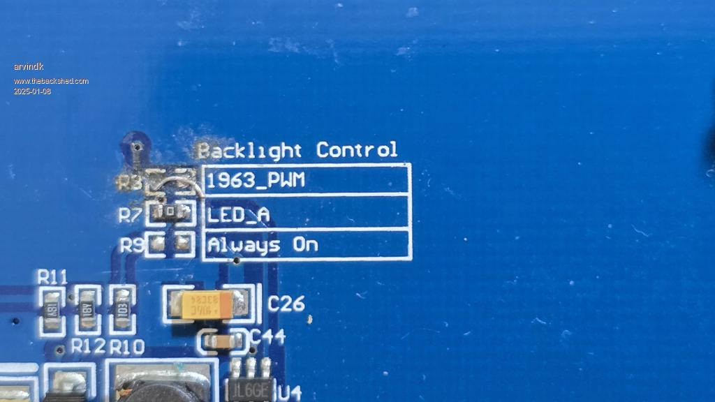 ak |
||||
| phil99 Guru Joined: 11/02/2018 Location: AustraliaPosts: 3293 |
Your photo shows both 1963_PWM and LED_A bridged - R7 is a 0Ω link. You need to remove one. It might be easiest to snip off the link you added to 1963_PWM and enable the LED_A option in option lcdpanel and add a wire from pin 12 of the MM+ to LED_A. MicroMite V5.05.05 contains the latest firmware version for the Explore64. Several new features and commands / functions. MMFlash doesn't need a PicKit 2, it uses an ordinary MicroMite2 or Arduino Nano as the programmer. This link will download a ZIP file containing it and all the documentation. https://www.c-com.com.au/stuff/MMflash.zip |
||||
| erbp Senior Member Joined: 03/05/2016 Location: AustraliaPosts: 195 |
Hi @Arvindk From your photo it looks doubtful that the left end of the link you installed at R3 (or is it R8) actually connects to the PCB track coming from the via in the PCB just above the label for the link. Also you still have the shorting link at R7 in place, although this may not matter if you didn't connect anything to the LED_A pin on the SSD1963 connector. In an earlier post you mentioned that you live in Pymble and asked if anyone could help you with this problem. I live in the Hills District in Sydney which is not really very far from Pymble, and I would be willing to assist you. I do have a 7" SSD1963 LCD that I know works, and I can also solder / de-solder the links on the back of your LCD PCB. If you would like me to assist, please do NOT attempt any further "fixes" to your LCD and send me a PM and we can see if we can arrange something. I do have free time this Friday (10th) Jan and possibly early next week too. Anyway if you want my help let me know via the PM. Cheers, Phil. Edit: I can also help you load the latest firmware if you want. Edited 2025-01-08 11:31 by erbp |
||||
| phil99 Guru Joined: 11/02/2018 Location: AustraliaPosts: 3293 |
@Erbp your direct input will be much more effective than our remote efforts. Driving 900km is beyond me now. If the area is too badly damaged perhaps move the 0Ω link to Always On as that should ensure the backlight works. Another option to bypass the damage could be a thin wire from 1963_PWM into the via above R8. |
||||
| arvindk Newbie Joined: 31/10/2011 Location: AustraliaPosts: 21 |
Thanks phil99. I completely mossed the 0 ohms. I thought all 3 were open. I tries to solder the 1963_PWM link. I did read the manual and knew that only one link is needed, but missed the link on LED_A. As for Quote 2, that example is not for SSD1963_7 but for the 5". I used the pins as shown in the manual/addendum for the 7". I have MMflasherand knew it does not need the Pickit 3. Whan worryied me was whether it works on the pic32 based explor64. Somewhere I read it worked on Micromite earlier desigms. So thanks for the link you sent.I will update my firmware. ak |
||||
| arvindk Newbie Joined: 31/10/2011 Location: AustraliaPosts: 21 |
Hi @erbp I have not yet learnt how to PM from The foerum. I would be delighted to PM you. How do I ? ak |
||||
palcal Guru Joined: 12/10/2011 Location: AustraliaPosts: 2039 |
Look right up the top of this page and you will see Private Messenger "It is better to be ignorant and ask a stupid question than to be plain Stupid and not ask at all" |
||||
| erbp Senior Member Joined: 03/05/2016 Location: AustraliaPosts: 195 |
As Palcal said - use 'Private Messenger' at the top of the page. When the Private Messenger window is displayed, select 'New Message'. When the New PM window is displayed, click the magnifier icon to the right to the 'Send to member' text box. In the Member Search window, enter erbp then click the Search button. Click erbp in the list displayed (should be only entry). The PM window will redisplay with 'Send to member' set to erbp. Enter the 'Subject' and 'Message' texts then click the 'Save' button. The message will be sent to me. |
||||
| Mixtel90 Guru Joined: 05/10/2019 Location: United KingdomPosts: 8911 |
@arvind Oh dear, I have a friend with the same eye problem - from the way she struggles I realise how difficult this stuff must be for you. :( Face to face help will definitely sort this out. :) A second quick and easy option is, as Phil suggested, simply snip your link and control the backlight using a wire link from the LED_A pin. The LED_A input is a simple driver transistor AFAIK. Mick Zilog Inside! nascom.info for Nascom & Gemini Preliminary MMBasic docs & my PCB designs |
||||
| arvindk Newbie Joined: 31/10/2011 Location: AustraliaPosts: 21 |
@Mock Thank you. "I get by with a little help from my friends" as the Beatles said.  ak |
||||
| arvindk Newbie Joined: 31/10/2011 Location: AustraliaPosts: 21 |
I need to record the extraordinaly help I have received from erbp to get my expore64 in good working order. The basic problem was the bad soldering on my part, However erbp visited me and when it needed more work, he undertook to "overhaul" the many problems. He also uploade the Ver 5.05 firmware, and gave me very comprehensive documentation on hard copy as well as a usb-stick.He is very organised and thoroughly professional in everything he does. I have learnt a lot from him and I an encouraged to finish some more projects if spite of by poor eyesight. Thanks to the forum and other members who also responded. ak |
||||
| The Back Shed's forum code is written, and hosted, in Australia. | © JAQ Software 2026 |
