
|
|
Forum Index : Microcontroller and PC projects : MM: How to measure AC?
| Author | Message | ||||
| Poppy Guru Joined: 25/07/2019 Location: GermanyPosts: 486 |
I made my setup for powering it and I have a question concerning the grounding, so not to fry it all up ... having not enough experience with MC�s on AC-issues ... actually none till now  I will use a different transformer, to be able to power the Duinomite up parallelly (via a fixed 6V outlet, AC but rectified and regulated, see Pics). Now I want to use the two wires from the 0-25VAC to measure, the red one to AIN and the black one to the Duinomite�s GND. Of course the V-Divider is missing, I am just talking generally! Is the grounding correct?  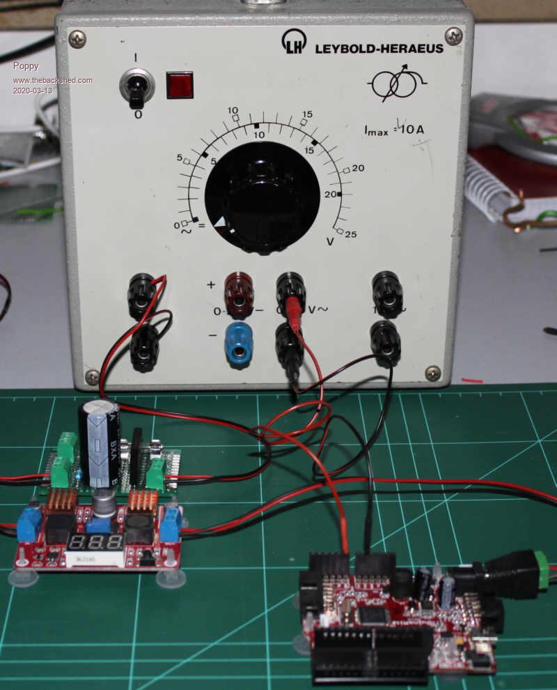 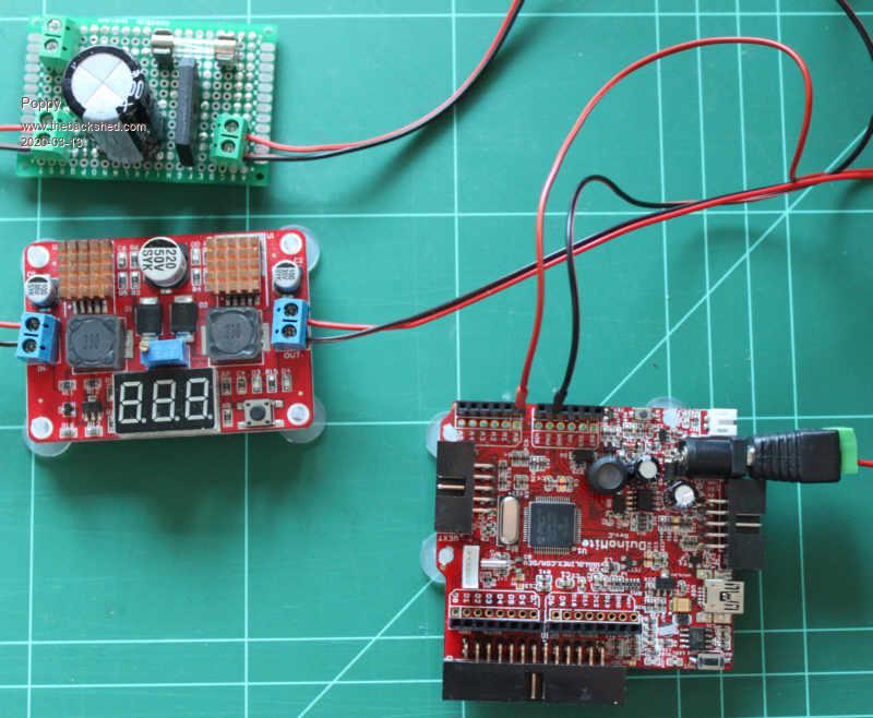 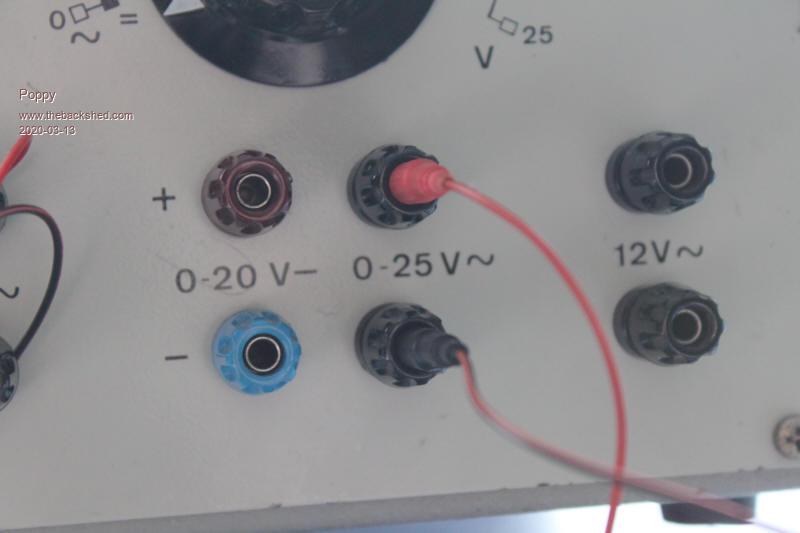 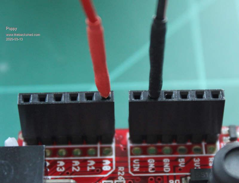 Andre ... such a GURU? Andre ... such a GURU? | ||||
TassyJim Guru Joined: 07/08/2011 Location: AustraliaPosts: 6538 |
Are you absolutely sure that your AC supply is fully isolated form the mains? There's going to be enough funerals in the coming months without adding one more. Jim VK7JH MMedit |
||||
| Poppy Guru Joined: 25/07/2019 Location: GermanyPosts: 486 |
I know. And thanks for caring!  It is a bit controversial, but as much as I interpret the old symbol on it independently ... on first sight it seems not to be, but technically it is (being checked!). It also is a former school-lab transformer (from the 80�s or 90�s, I guess) complying with certain practical standards (but apparently not following current labeling). Additionally I always have a 30mA-RCD set between in case mains could unexpectedly break through myself to ground. Generally I also do have some 230V-Isolating Transformers I could set between to separate from mains grounding, but I rather prefer RCD�s. I also own some other older low voltage supplies being checked up for isolation as well, but not �having an old-standard and therefore confusing symbol on them. The following first 2 ones are from old Western-Germany and the last one from old GDR, but all are in good shape and of great solid quality. I got those just for AC, my DC-supply of course is a little more up-to-date. PS: My question concerning grounding the DM was not about frying it (and myself) up with 230V mains but 25VAC. 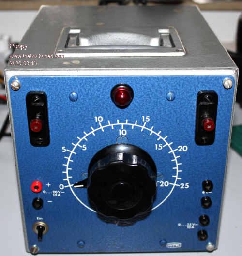 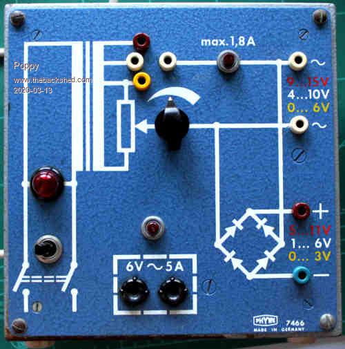 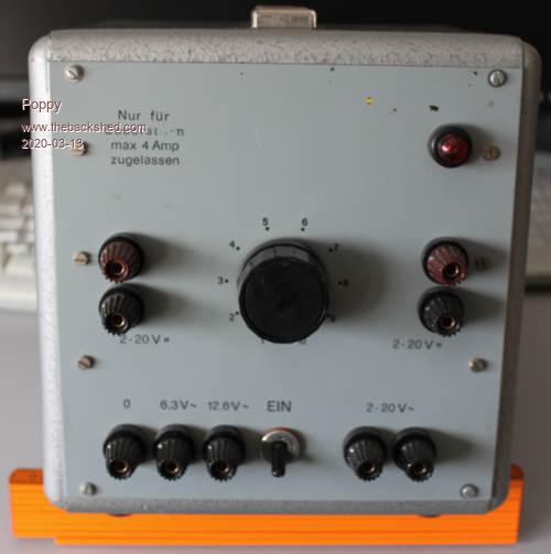 Edited 2020-03-13 17:39 by Poppy Andre ... such a GURU? | ||||
| Poppy Guru Joined: 25/07/2019 Location: GermanyPosts: 486 |
PPS: The western ones were built some time ago but they were still officially in use and technically maintained according to legal instructions until 2018, before I got them. Then I additionally checked them up myself concerning isolation as well. Andre ... such a GURU? | ||||
| Volhout Guru Joined: 05/03/2018 Location: NetherlandsPosts: 5931 |
Hi Poppy, Just make sure the AC input signal you apply to the Duinomite is not electrically connected to the voltage you use to power the duinomite (*). Best is if you use 2 different boxes (you seem to have plenty of them), and make sure they isolate from the mains. Regards, Volhout (*)= the AC voltage you measure is directly connected to the GND of the Duinomite. The power you use to power the Duinomite is rectified, then regulated to 5V. If both are connected in anyway, you bypass the rectifier -> smoke.... Therefore, use 2 different transformers for power and measurement signal. PicomiteVGA PETSCII ROBOTS |
||||
| Poppy Guru Joined: 25/07/2019 Location: GermanyPosts: 486 |
The goal is to get it all set up with one single transformer as I am planning to built up a supply delivering AC and DC parallelly. Just like the second one in the picture row (with the schematics on it). The basis will be such a white safety-transformer shown on the very first picture (next to the Phillips regulator). Now finally the power for the DM will come from it being rectified and regulated, but the measuring access as well. The 3.3 VDC supply shall come from the built-in regulator of the DM, if possible to realize that way. Hooking it up for testing it is no problem to use any other supply parallelly, but finally I have to be sure not to smoke it up being supplied by a single source. PS: I get the general problem, it is just like any oscilloscope-issue ... Edited 2020-03-13 18:48 by Poppy Andre ... such a GURU? | ||||
| Poppy Guru Joined: 25/07/2019 Location: GermanyPosts: 486 |
I think I got it together now, at least theoretically. For my aim running one single transformer this way won�t work unless I will power the DM with a battery, so I would just be building an external Voltmeter. I will generally need two isolators! First way: 2 separated transformers parallely isolating on primary side, the first powering the whole supply and the second exclusively powering the DM. Second way: One general transformer isolating primary to secondary side and then a second small transformer isolating the DM exclusively on the secondary side, just like such a small 12V to 12V HiFi-Decoupler. This way I could easier take this AC-Sensor-Module shown in the beginning of this thread actually being nothing different in my opinion]. I cannot see an easier way without frying my DM.  PS: Those HiFi-Decoupler seem not to be matching for being different than I thought. Edited 2020-03-13 19:26 by Poppy Andre ... such a GURU? | ||||
| Poppy Guru Joined: 25/07/2019 Location: GermanyPosts: 486 |
For the sake of some junior grade physics I just made a little setup, showing lacking accuracy and practicability ... Simply measuring RMS before a single bridge rectifier and DC after it. 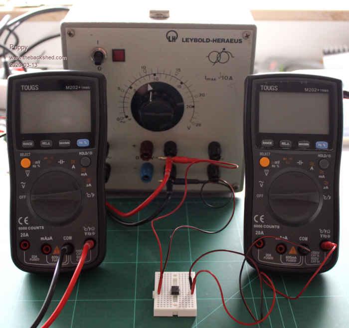 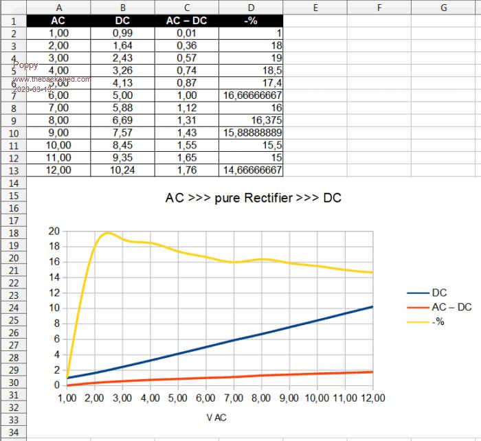 Andre ... such a GURU? Andre ... such a GURU? | ||||
| Volhout Guru Joined: 05/03/2018 Location: NetherlandsPosts: 5931 |
Hi Poppy, Interesting measurement results, but question is ... what are you trying to accomplish ? In essence, the bridge rectifier will change the sine wave into a rectified sine wave. But it has diode forward voltage drop (depending the current). The multimeter presents a very high impedance load, so the current is almost 0. Because of this the forward voltage drop of the rectifier will be completely unpredictable. Secondly: the multimeter that supposed to measure DC, performs some kind of averaging. But since that is not documented, you are not sure what it exactly does. A fast multimeter will jitter a lot, a slow multimeter does ..??? Anyway... nice photo and graph of the experiment. I am sure the duinomite will do a better job with accuray... Regards, Volhout. P.S. make sure the TOUGS M202 multimeter actually measures RMS. Some cheap multimeters measure peak, and divide by 1.4. PicomiteVGA PETSCII ROBOTS |
||||
| Poppy Guru Joined: 25/07/2019 Location: GermanyPosts: 486 |
Simply comparing different approaches free of any prediction, just a philosophical matter ... simply having some short fun with it while preparing different issues. The rest you constructively point on are clear, but that was not my task, sometimes I just want to actually see something in reality. You are right, haven�t actually checked them, so relying on something being unquestioned goes against my maxim, but for my modest demand they have been doing a fair job so far. Andre ... such a GURU? | ||||
| Poppy Guru Joined: 25/07/2019 Location: GermanyPosts: 486 |
PS: The Multimeters literally claim to be "True RMS" but they are still cheap chinese stuff (were about 20-25 Bucks each), so generally questionable! Andre ... such a GURU? | ||||
| Poppy Guru Joined: 25/07/2019 Location: GermanyPosts: 486 |
Yeah, still rocking!  Making another short stop on my way finally frying my Duinomite Just for the sake of some more practical visualization concerning the linearity and therefore opportunity to conclude the primary voltage by exclusively measuring the secondary ... My setup is a safety transformer (mains to "12VAC", the white block) being regulated on the primary side (by the Phillips) and being measured parallelly on both sides. Disregarding some impreciseness it is quite obvious, probably using 2 "AC-Sensors" parallelly both could be calibrated against each other. 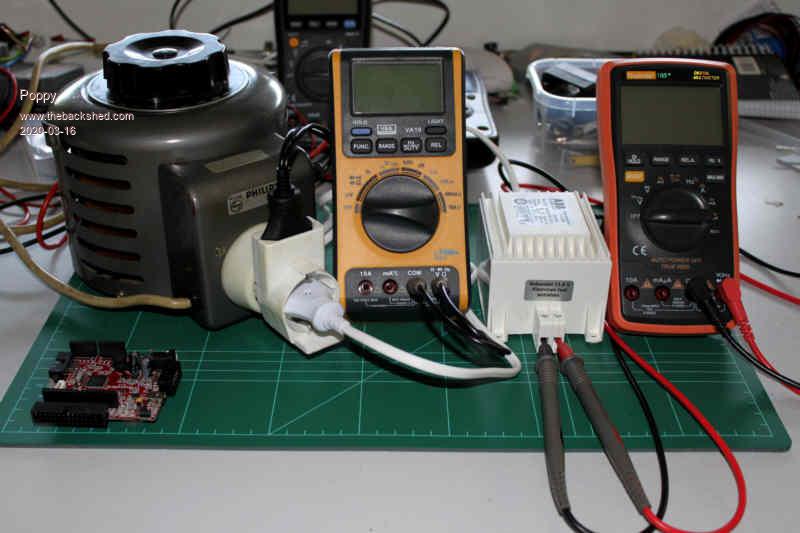 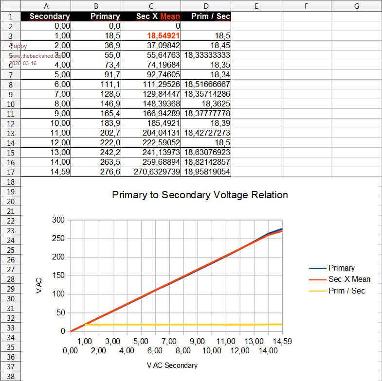 Andre ... such a GURU? Andre ... such a GURU? | ||||
| Volhout Guru Joined: 05/03/2018 Location: NetherlandsPosts: 5931 |
Hi Poppy, Thedifference between the orange line versus blue line is due to saturation of the iron core of the white transformer. Typically transformers are designed to handle 220/230V + 10%, but at +20% they start to show losses (they also get warmer). Regards, Volhout P.S. the Philips transformer does not suffer these losses since it is connected to a solid 230V. You only vary the tap on the output winding. PicomiteVGA PETSCII ROBOTS |
||||
| The Back Shed's forum code is written, and hosted, in Australia. | © JAQ Software 2026 |
