
|
|
Forum Index : Microcontroller and PC projects : CMM2 - Maximite2 Kit v3.0 PCB build notes
| Author | Message | ||||
| Amnesie Guru Joined: 30/06/2020 Location: GermanyPosts: 763 |
Hello, I tried the above program with my Wavesahre 400Mhz "y" version board. No problems at all. Crisp & clear audio. And because I can't source the audio connector in germany I even soldered unshielded wires to an external connector! But I built everything upon the PCB Vers. 2.1 with the upstanding resistors. I dislike the smd & "all in one soloution" because I want to be able to plug & unplug the module in case I had a drink too much and burning the board by fiddeling with my sensors and the 40 pin connector. The resistor-networks are cool but you can't source them as easy as single resistors. So I am happy that those 3 versions exists! What a great little board and software! Greetings Daniel Edited 2020-07-12 22:31 by Amnesie |
||||
| Womble Senior Member Joined: 09/07/2020 Location: United KingdomPosts: 267 |
Thank you Peter for clarifying things ... I was wondering if it might be Waveshare related, and was considering getting another Waveshare to test/compare. Just my luck to get a rogue board.  I note your comments regarding the crystal and will order myself the parts for the oscillator mod. Your help with this is very much appreciated. |
||||
| Womble Senior Member Joined: 09/07/2020 Location: United KingdomPosts: 267 |
Daniel, thanks for posting your test. It as I suspected, a problem related to my hardware. Peter has kindly pointed out that the Oscillator Mod should fix my problem. Which it turns out is probably a slightly out of spec Waveshare. That is precisely why I went for the Waveshare version, so I could swap out the cpu if I screwed the machine up whilst tinkering (or building the kit). I'll second that ... excellent little machine ... Many Thanks to the Dev Team |
||||
| Womble Senior Member Joined: 09/07/2020 Location: United KingdomPosts: 267 |
Peter, are these the correct parts you referred to above? LFSPXO018045 Oscillator, Crystal, 8 MHz, 50 ppm, SMD, 7mm x 5mm, 3.3 V, CFPS-73 Series https://uk.farnell.com/iqd-frequency-products/lfspxo018045/crystal-oscillator-smd-8mhz/dp/9713468?st=0705%208Mhz%20oscillator http://www.farnell.com/datasheets/2551800.pdf Size: L: 3.2mm W: 1.6mm H: 0.55mm Footprint: SMD 1206 Package formation: SMD tape 100nF: 16V +/- 10% https://www.ebay.co.uk/itm/1206-SMD-Capacitors-90-Values-Available-10-Pack-UK-SELLER-Same-day-dispatch/264566930175?ssPageName=STRK%3AMEBIDX%3AIT&var=564323940840&_trksid=p2060353.m1438.l2649 eBay item number: 264566930175 Any idea which way round the Oscillator goes? It does not appear to be marked on the v3.0 board or included in the schematics. 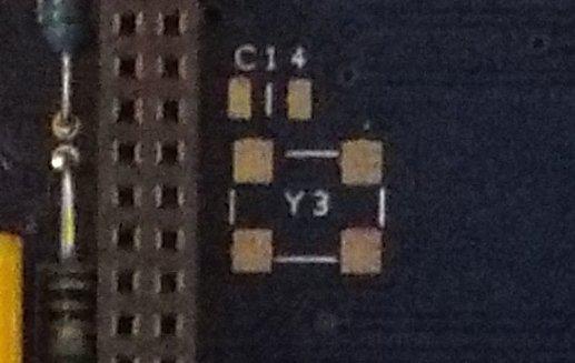 Your comments would be greatly appreciated. Roy (aka. Womble) |
||||
| matherp Guru Joined: 11/12/2012 Location: United KingdomPosts: 11668 |
You can just see the pin 1 dot in your picture - top right Parts should be fine. Be very careful soldering the oscillator that the solder doesn't wick up onto the case. It will probably work even if you leave the crystal in place on the Waveshare but it does kill the crystal |
||||
| Womble Senior Member Joined: 09/07/2020 Location: United KingdomPosts: 267 |
Thanks for your prompt reply Peter. I had missed the DOT in the picture Ā  Edited 2020-07-13 02:41 by Womble |
||||
| KeepIS Guru Joined: 13/10/2014 Location: AustraliaPosts: 2203 |
Been meaning to fit these for a while, so just ordered an Xtal and cap, looking forward to seeing how this goes. NANO:Inverter V 8.2ks -┬ĀLinux AvrDude GUI script V4.1 |
||||
| Womble Senior Member Joined: 09/07/2020 Location: United KingdomPosts: 267 |
Ordered from Farnell. Caps arrived today (15th July), oscillator is coming from Belgium, hopefully tomorrow. I will post how I get along. Bit nervous about the surface mount soldering. |
||||
BobD Guru Joined: 07/12/2011 Location: AustraliaPosts: 935 |
Got my CMM2 from Big Mik today. It's the surface mount board. If Mick soldered the processor then he has done a top job as is also the rest of the board. Haven't run it yet as I'm a bit busy today. Very professionally presented and supplied.  |
||||
| Womble Senior Member Joined: 09/07/2020 Location: United KingdomPosts: 267 |
Fitted mine this morning. Managed a neat job with the Oscillator, but the capacitor was a real b@#%$r. There is not a lot of room to get to the cap, even with a fine tip iron. So glad I fitted the Oscillator first. Peter, you were bang on regarding the video issue. The Oscillator mod fixed the picture tearing nicely. I am still getting audio noise though. Tried multiple PC speaker setups, and different audio cables. I am currently using a nice well shielded cable with a ferrite core at the CMM2 end. It still buzzes. Particularly when using Files and the Editor. Any suggestions before I go order another Waveshare ? Regards Womble |
||||
| Womble Senior Member Joined: 09/07/2020 Location: United KingdomPosts: 267 |
I didn't desolder the Crystal, and it still works. The video tearing is gone Sorry Waveshare Crystal  I hope thats not what is causing the noise/buzzing issue |
||||
| Womble Senior Member Joined: 09/07/2020 Location: United KingdomPosts: 267 |
Oh, and I have tried multiple power sources to rule out mains hum. I am running v5.05.04RC3 at the moment, but the problem also happens with earlier builds loaded. The noise is alost gone at the boot up screen, but isse a FILES command, or go into EDIT mode and there is a constant buzzing. As noted previously BUCKY.BAS clicks on every animation update. The volume and amount of buzzing seem to be related to the video mode or amount of SD access. I'm mystified by this one. |
||||
TassyJim Guru Joined: 07/08/2011 Location: AustraliaPosts: 6549 |
Does the buzz remain when you turn the monitor off? Have you tried a ground loop isolator in the audio line? Jim VK7JH MMedit |
||||
| Womble Senior Member Joined: 09/07/2020 Location: United KingdomPosts: 267 |
Good thought Jim ... will try tomorrow. Not heard of (nor do I have) one of those. ĀThis is a new prolem to me. ĀI googled the device, and can see what you are referring to. Ā I will ask around and see what I can borrow or source. I'm not giving up on this. ĀI like the CMM2 too much, its great fun, and is getting me coding again. Ā Hopefully I can contribute to the community once I get my head around the differences between MMBasic and the GWBasic/Powerbasic I used so often in the (dim and distant) past. Your help is appreciated. Womble Edited 2020-07-17 08:50 by Womble |
||||
| Paul_L Guru Joined: 03/03/2016 Location: United StatesPosts: 769 |
You will not be able to buy a ground loop isolator. If you have multiple conductors connecting grounded devices a circulating current can occur in the ground loop. You should break all but one of the interconnecting ground conductors. The broken conductor is the ground loop isolator. Audio lines are very often shielded, but the shield should only be connected to a ground at one end of the audio cable when there is another conductor, perhaps the low side of the power supply, connecting the system grounds together between boards. The break in the shield connection avoids the spurious current flowing in the shield which will be amplified with the audio. What you hear is the amplified AC line ripple voltage which creeps through the power supply to the supposedly flat line DC supply. Only a battery produces a flat line voltage. Paul in NY |
||||
| Womble Senior Member Joined: 09/07/2020 Location: United KingdomPosts: 267 |
Paul, many thanks for your concise explanation. Using a battery (eg. usb power bank) to power the CMM2 was on my list of "things to try" to discover what was causing the noise, and hopefully fix it. Currently my setup uses a usb phone charger wall wart (transformer based psu, live and neutral connected to 240v 50hz ac) powering the CMM2. The monitor has built in amplified PC audio input and is powered by the manufacturer provided switched mode power brick. I am in the process of trying different power supplies, monitors, speaker setups, etc. Not giving up yet. |
||||
| morgs67 Regular Member Joined: 10/07/2019 Location: AustraliaPosts: 78 |
This is the type of isolation transformer that should work: https://www.ebay.com/itm/5PCS-EI14-EI-14-Audio-Coupling-Isolation-audio-Transformer-600-600-L40/114247602420?hash=item1a99b010f4:g:2xoAAOSwy2pbtgQr This is an example of the transformer type only. You may need a capacitor in series with the signal from the micro to the transformer input side. One winding between the output of the CMM2 and CMM2 ground, the other winding between ground of AMP and Amp input.( Do not connect the grounds together at this point.) tony |
||||
| Womble Senior Member Joined: 09/07/2020 Location: United KingdomPosts: 267 |
Thanks for the info Tony, I will investigate Edited 2020-07-17 22:27 by Womble |
||||
| KeepIS Guru Joined: 13/10/2014 Location: AustraliaPosts: 2203 |
Just as a second update to Womble fitting his xtal. I just received the 8MHz xtal and fitted it, I removed the existing xtal first just in case I needed it. Retrofitting the xtal module is a pain. Solder paste was no good as once the header sockets are soldered in, there is no room to get a fine tip soldering iron at the right angle, there is no lead length at all on the xtal case. I wasn't game to try my soldering heat gun even with a tiny nozzle as it would likely melt the plastic 80P header socket. Anyway, fitted it neatly in the end and happily, all video noise has now completely disappeared for me as well. It was getting worse with each passing day, and especially once the CMM2 warmed up. If I build another CMM2 I'll just order the xtal and cap straight off the bat. NANO:Inverter V 8.2ks -┬ĀLinux AvrDude GUI script V4.1 |
||||
| Womble Senior Member Joined: 09/07/2020 Location: United KingdomPosts: 267 |
I agree 100% When I fitted the crystal oscillator. Do this first!!! I tinned the pads on the pcb, used solder wick to make sure there was only the smallest amount of solder bulge on the pad, applied some liquid flux, and tacked each of the 4 corners with a hot needle point iron. This did a neat job for me. As mentioned previously, be very careful not to create a short with the metal lid on the oscillator. Pin One on the oscillator is a different shaped pad on the underside of the device. (I grabbed this from the datasheet) 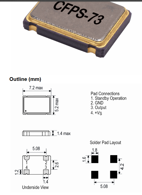 Then I had a go at the "grain of rice" (capacitor). The same technique worked, but it is not pretty or flush to the pcb. The capacitor is not polarised and can go either way around. A magnifying glass, tweezers to hold compnents in place and a pointy iron got the job done ... even for an amateur hobbyist like me. Fitting these to the pcb before assembling the waveshare headers would be a good idea if you get the chance. |
||||
| The Back Shed's forum code is written, and hosted, in Australia. | © JAQ Software 2026 |
