
|
|
Forum Index : Microcontroller and PC projects : How to connect multiple Nunchuks to CMM2
| Author | Message | ||||
mclout999 Guru Joined: 05/07/2020 Location: United StatesPosts: 509 |
Thanks for this I missed it somehow. Very Nicely done. They call me Shai-Hulud (The maker) |
||||
| lizby Guru Joined: 17/05/2016 Location: United StatesPosts: 3784 |
I'm finding conflicting information on the intertubes regarding the pins. Can someone confirm (or dis-) that when you are looking into that Wii/Nunchuk socket that has the pins which connect to a PCB, with the notch on the bottom, this is the layout of the socket pins? Connector Socket --------- | 1 2 3 | | 4 5 6 | |__---__| 1 Data I2C Data line 2 ACC used by the remote to detect presence of the Nunchuk � � � �(pin 2 and 3 shorted in Nunchuk to give 3.3V back to remote when Nunchuk is connected) 3 +3.3V VCC 4 GND Ground 5 N.C. No Connection 6 Clk Clock (100KHz) ~ Edited 2020-07-27 10:52 by lizby PicoMite, Armmite F4, SensorKits, MMBasic Hardware, Games, etc. on FOTS |
||||
TassyJim Guru Joined: 07/08/2011 Location: AustraliaPosts: 6538 |
Peter, thanks for pointing out my error re pullups. I should have known that. Quazee, Your schematic lists pin 1 as being GND (as well as 3.3V) It is 3.3V Lizby, I have seen pin 2 listed as the 3.3V but usually it's pin 3. Most cables will have pins 2 and 3 shorted as presence feedback so it shouldn't matter. I would have prefered pin 2 as the VCC so that connecting the wrong way arround is not an issue but I guess the designers of the nunchuk reckoned the physical shape of the case cutout is sufficient. I have seen some silly connectors in my day, but this would have to be one or the worst. 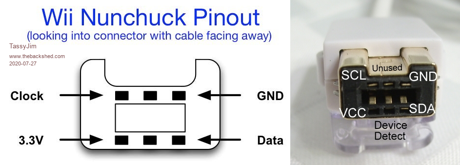 Jim VK7JH MMedit |
||||
| lizby Guru Joined: 17/05/2016 Location: United StatesPosts: 3784 |
Thanks, Jim, With respect to the notch, which is down in my diagram but up in yours, I think our labeling of the signals is the same. I don't know if there is any standard for numbering the pins. PicoMite, Armmite F4, SensorKits, MMBasic Hardware, Games, etc. on FOTS |
||||
| TassyJim Guru Joined: 07/08/2011 Location: AustraliaPosts: 6538 |
Most images I have seen put the notch on top. The CMM2 has the notch on the bottom so that the connector fits in without having to put the CMM2 case on a pedestal. VK7JH MMedit |
||||
Quazee137 Guru Joined: 07/08/2016 Location: United StatesPosts: 603 |
Yea Jim I did see that. Its what happens at the end of a 36 hour day. Its not part of the wiring just a note area I forgot to remove before making the image to post. The way I did the board was so if any one wanted to just wire to a plug in header could do so. That is why the split 3.3V and the grounds. I am wondering why take up all I2C's for this when the front one can be multiplexed to do 1,2,4 and even 8 with the base code just pointing to each port. The code is beta right? things being hammered out and all. By by using a 12 channel I2C ADC can give most what has being wanted by using the back 40 pin. The front facing NunChuk port makes easy hook up. And pairing this up with the two NunChuk multiplexed board I added else where could do two of the XYZ analog and 9 buttons too. The main thing is I do not know how much time any game would need to read the controller/s and not weight one over the other. I did read some where here that the NunChuk code is ran in the back ground. By talking to one I2C getting data then pointing to next attached with same code IMHO would be faster than using all three I2C's but then I don't code in C. I was mostly thinking how the old game systems ended up adding more ports some with a 4 port plugged into port one of system. The PS, Game Cube ect.. Any board design I do that is wanted will be open so any one can make them. Just my part of giving back to MMbasic and Mites that have made the custom hardware designs I do for money so fast and easy to update. My customers are very happy to get the code so they can make it even more to their liking or when needs change a bit do to newer sensors and valves. Most of them are like "WOW I can read this and even add to the code" Unlike my old asm way that took weeks/months to do is now just a few days. Sorry Im tired looong day and I rant when this tired. have FUN be SAFE Quazee137 |
||||
| darthvader Regular Member Joined: 31/01/2020 Location: FrancePosts: 100 |
Hi , Not so long ago i have use this I2C Multiplexer : I2C Multiplexer It worked perfectly with STM32F7 / H7 and ESP32 With this one , you just use the nunchuck connector pins , but , the channel that you read/write (1 to 8) have to be selected before use to ensure that you read the correct nunchuck or what ever you attached to the multiplexer. Cheers. Theory is when we know everything but nothing work ... Practice is when everything work but no one know why ;) |
||||
| lizby Guru Joined: 17/05/2016 Location: United StatesPosts: 3784 |
Is there any nunchuk-ready CMM2 program, 800x600 mode only, since that appears to be all my monitor accepts? PicoMite, Armmite F4, SensorKits, MMBasic Hardware, Games, etc. on FOTS |
||||
| mclout999 Guru Joined: 05/07/2020 Location: United StatesPosts: 509 |
What about these $1.77 free shipping? FLEABAY!! I think they are functionaly equivalent. The one you list is 7.90 + Shipping so if this is a good option LETS go for a cheap breakout board. https://tinyurl.com/y3gtlap8 Edited 2020-07-28 07:10 by mclout999 They call me Shai-Hulud (The maker) |
||||
| The Back Shed's forum code is written, and hosted, in Australia. | © JAQ Software 2026 |
