
|
|
Forum Index : Microcontroller and PC projects : CMM2 clone PCB
| Author | Message | ||||
manawyrm Newbie Joined: 30/07/2020 Location: GermanyPosts: 5 |
My CMM2 already has 32MB of RAM instead of 16MB. More is also possible, just order a different chip (footprints are compatible). You'll also need to recompile / modify the CMM2 software to use the additional RAM. HDMI would also be possible, there are a couple of nice chips from Analog Devices that can take the output of the STM32's LTDC and turn it into nice and crisp HDMI video. That would require slight changes to the VGA code though (for timing reasons). These chips are not available for assembly at JLCPCB though and I also don't have a spare HDMI monitor, only VGA. So I'm not going to do that :) This sounds like an ideal beginners project to learn PCB design ;) An adapter from the 40pin extension header to 2x 9pin joystick would be very easy to do and a great learing experience... |
||||
| mkopack73 Senior Member Joined: 03/07/2020 Location: United StatesPosts: 261 |
How the heck much RAM do you think is needed in a machine like this??? 16MB is already WAYYYY more than we ever had in either the 8 or the 16 bit era!!! I had an A500 back in the day with 9MB RAM and that was like HUGE for the time. So really,what the heck are you all doing that you feel you need more than we have currently?? |
||||
| JoOngle Regular Member Joined: 25/07/2020 Location: SwedenPosts: 82 |
Nice! I overlooked that little information candy bit :) Sure! But the idea is to have it all on one PCB, because the majority won't be adding or purchasing the extra expansion, but it will increase the general audience's use of the CMM2. Well, with that kind of counter-argument for or against, we might as well add the fact that the Commodore 64 was roughly 1 MHz in speed, and the base Amiga was about 8 MHz in speed. The CMM2 is a whopping 400 MHz (albeit Risc architecture) for comparison. |
||||
mclout999 Guru Joined: 05/07/2020 Location: United StatesPosts: 509 |
You device has 32mb Ram!!!!? The standard CMM2 has "2MB of flash. 1MB on-chip RAM plus 8MB off-chip" How much of that 32mb of ram is on-chip and how much is of-chip and what Chip exactly did you use. Also how much flash dose that chip have? They call me Shai-Hulud (The maker) |
||||
| mkopack73 Senior Member Joined: 03/07/2020 Location: United StatesPosts: 261 |
Can the system even USE all of that??? I mean, I would think the MMBasic has some fixed tables set up for things like the variable space and such. If you can get it to use all of it, cool, but you're likely still going to be limited by the variable space and such... Maybe Peter can do something to make the firmware be able to use more if it's available? I guess I'm just struggling to figure out what would use so much RAM on a system like this... Even some of the most advanced stuff we've seen so far on this platform (MauroXavier's Gauntless and Wolfenstein ports) likely don't use all the RAM yet. |
||||
| matherp Guru Joined: 11/12/2012 Location: United KingdomPosts: 11513 |
The CMM2 has a 64Mbit/8Mbyte SDRAM chip manawyrm's PCB uses a 128Mbit/16Mbyte chip. 16Mbyte is the absolute maximum that the 176 pin H743 chip can support on a single SDRAM chip. To go more you would need a second SDRAM chip or a different processor chip with more pins. In any case the CMM2 firmware and the official hardware designs only supports 8Mbyte and this isn't going to change. As previously discussed on other threads the best way to bu..er this project is to have multiple types of incompatible H/W a la Raspberry Pi such that some software can only run on some variants manawyrm's PCB is a really nice design and probably electrically superior to the current versions but I personally disagree with some of the design decisions: 4-layer even more cluttered back panel SMD connectors hard to hand solder and, like all other versions, not available to be installed by JLC Crystal instead of oscillator micro-SD no switch no mounting holes (re-work needed to accommodate) If you want to get PCBs made up and populated by JLC I have previously posted the gerbers for the all-in-one design (V1.5) used by our various vendors. Cost would be the same or cheaper than this version (2-layer PCB) but with the one disadvantage that the SDRAM is on the bottom and needs to be hand soldered as JLC only support single sided SMD assembly. |
||||
| RetroJoe Senior Member Joined: 06/08/2020 Location: CanadaPosts: 290 |
I too am missing the point of this surface-mount clone, other than the intellectual challenge, which is unarguably formidable. But, it seems like a missed opportunity to innovate and extend the Maximite platform. IMHO: 1) A cool thing would be to refactor the CMM2 to be the same size as a Raspberry Pi 4, and with a bit of Dremel surgery, enable the use of existing RPi4 cases (eyeballing my RPI4, it looks like the 2X2 USB + RJ-45 area would be plenty of space for the CMM2's VGA jack and the two USB's, and maybe even the Wii connector). 2) An on-board HDMI option would be very cool too - the smaller size and an HDMI "display anywhere" capability would make the CMM2 even more portable, and would make the decision to use a microSD slot more logical i.e. I see no advantage to microSDs unless you need to save space - full-size SD cards are much easier to manipulate, and a lot harder to lose in desk drawers and dimly-lit basements :) 3) RPis don't have power switches either, but it's obvious most users want one, as the current trend with the RPi4 are power supplies with in-line power switches. Unplugging a power supply to reboot seems so Neanderthal! 4) Finally, many retro computers had a mono speaker. A little onboard piezo speaker would be kinda cool (see Item 2 above), and could maybe be used to issue "POST" beep codes in future FW updates. Cheers, Joe P. Enjoy Every Sandwich / Joe P. |
||||
| Geoffg Guru Joined: 06/06/2011 Location: AustraliaPosts: 3362 |
HDMI is never going to happen (other than via a VGA converter). The STM32 cannot be made to generate HDMI so an additional complex chip will be required plus the HDMI specification is not an open standard and implementations need to be licensed by HDMI LLC (ie, $$$$). Geoff Geoff Graham - http://geoffg.net |
||||
Grogster Admin Group Joined: 31/12/2012 Location: New ZealandPosts: 9975 |
@ matherp: 100% agree with that, and as I was part of the CMM2 development team....... I FULLY ACKNOWLEDGE that manawyrm's PCB is a real masterpiece, but the system will NEVER support the 16MB that he has put on his board, as 8MB is the maximum that will ever be supported. Putting bigger SDRAM chips on the board DOES NOT mean that MMBASIC for the CMM2 firmware can actually address that - it is currently fixed at 8MB, so having a 16MB SDRAM chip probably will work, BUT it will never be able to address more then 8MB of that chip. So, the idea of adding a bigger SDRAM chip to the CMM2 design in the hope that it will be able to address that extra SDRAM in the same way as you add extra RAM to a PC is false logic. The CMM2 system hardware specs are SET. You CAN'T just add extra things like in a PC, and expect them to work. The CMM2 firmware EXPECTS certain things to be constant, and an 8MB SDRAM is one of those things. @ RetroJoe and Geoff: #1 - Never going to happen. It was a massive squeeze to get the CMM2 into two-layer, and to do that, would require multi-layer versions. Sure, people COULD make their own multi-layer versions that DID fit the Pi footprints, but these PCB's would NEVER be supported by the official firmware. #2 - Lovely idea, but also never gonna happen. Using HDMI in ANY commercial product requires licencing as Geoff mentions, and that is simply never gonna happen on the CMM2 for that exact reason. #3 - CMM2 has an on-board power switch. #4 - Nice idea. I like this one. Perhaps this can be accommodated in future firmware updates and/or PCB releases. Smoke makes things work. When the smoke gets out, it stops! |
||||
| frnno967 Senior Member Joined: 02/10/2020 Location: United StatesPosts: 105 |
 If this case+keyboard was a reality I would buy it tomorrow. And it would be great to have an ESP added to the design for a serial Wifi modem like we've been discussing in another thread. :) Jay Crutti: Ham Radio Operator, K5JCJ. Computer Enthusiast. Musician. Engineer. |
||||
| RetroJoe Senior Member Joined: 06/08/2020 Location: CanadaPosts: 290 |
Yep, that case rendering is a beauty - hope it becomes a reality some day! Somewhat related, I have no personal desire to own a “PiMite” or whatever such a form factor would be called, but there is something inherently intriguing about a credit card sized computer :) Apart from that, the CMM2 reference PCB is already “too small” if you’re comparing it to the classic 8-bit computers (IIRC, the Sinclair ZX PCBs were approximately the same size as the CMM2’s). And, totally get the HDMI technical and commercial constraints. It’s a shame; I’ve always felt that HDMI’s proprietary nature and integrated DRM killed off a huge amount of potential innovation. It’s defacto what’s made VGA the best (and sometimes only) video option for hobbyists and low-volume production, and the CMM design is particularly “Woz-like” in its clever implementation. On that note, one interesting approach to circumventing the HDMI homebrew constraints is to use an entire SBC as an “HDMI server”. For any Apple II owners, below is the “VidHD”, which uses an Orange PI SBC piggybacked on an Apple II expansion card, with firmware that scans the Apple’s display memory and outputs it through HDMI. A particularly impressive bit of engineering given the Apple II’s notoriously convoluted video system! I bought one last year, and it works great, but some of the hoped-for upgraded firmware capabilities (in particular, using the Orange Pi’s on-board Wi-Fi) have not yet materialized - the antenna you see in the pic is as useless as the proverbial teats on a bull :) It’s a dramatic contrast to Peter and Geoff’s torrid pace of innovation and FW releases ! 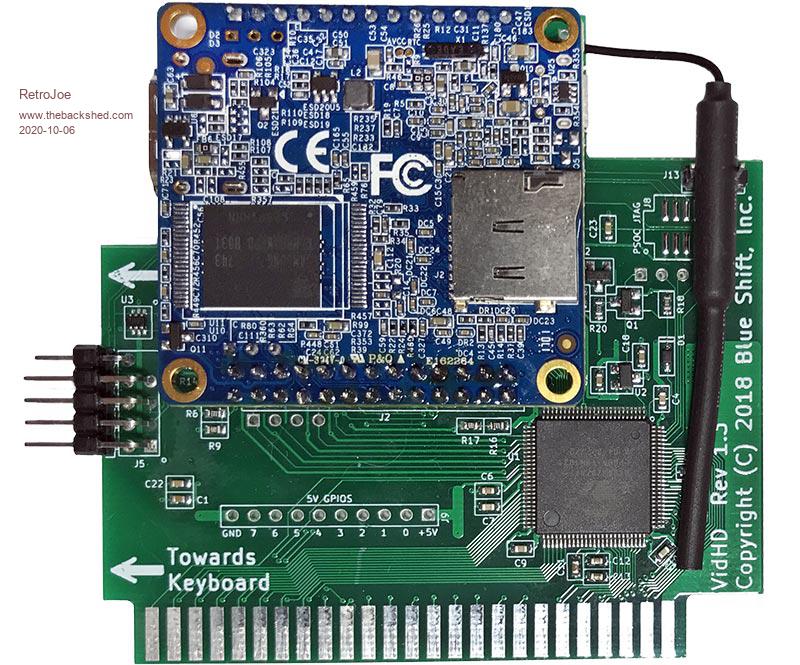 Edited 2020-10-06 03:42 by RetroJoe Enjoy Every Sandwich / Joe P. |
||||
| Sasquatch Guru Joined: 08/05/2020 Location: United StatesPosts: 385 |
You can also use DVI-D. The digital RGB signals are the same as HDMI and only require a simple passive adapter to connect to HDMI displays. Unfortunately, DVI does not support audio so it's not as nice as a native HDMI output with combined audio/video. -Carl |
||||
| The Back Shed's forum code is written, and hosted, in Australia. | © JAQ Software 2026 |
