
|
|
Forum Index : Microcontroller and PC projects : CMM2: Garbled MP3 sound
| Author | Message | ||||
| paceman Guru Joined: 07/10/2011 Location: AustraliaPosts: 1329 |
Yes, I had read that but it does say The output is high impedance suitable for feeding into an amplifier. That's exactly what I'm doing, i.e. "feeding into an amplifier" but it produced the problem. I'm pretty ignorant about amps (less so now thanks to you all and this thread) and I reckon that description should be "amplified"  a bit. Probably just adding, as you said, "It needs a load of at least 5K which can be achieved by adding an inline 4.7K series resistor if your amp/speaker sounds garbled &/or lacks its normal bass". a bit. Probably just adding, as you said, "It needs a load of at least 5K which can be achieved by adding an inline 4.7K series resistor if your amp/speaker sounds garbled &/or lacks its normal bass".Also I reckon a comment re blocking capacitors just after the part "The signal level at full volume is about 1V RMS (approx 3V peak to peak)" would be helpful, maybe along the lines of "The DC offset of the output, which is necessary because of the single supply of the CMM2, means that amplifiers must incorporate a series blocking capacitor. Most amplifiers will already have this but if not, a 1 or 2uF series capacitor should be added to the output" - or somesuch! What do you reckon?  Greg |
||||
| Geoffg Guru Joined: 06/06/2011 Location: AustraliaPosts: 3362 |
Sounds good. Check the next release. Geoff Graham - http://geoffg.net |
||||
| paceman Guru Joined: 07/10/2011 Location: AustraliaPosts: 1329 |
Thanks Geoff, I think it will help quite a few users. I think a lot of gamers would not be overly electronics savvy. |
||||
| Paul_L Guru Joined: 03/03/2016 Location: United StatesPosts: 769 |
It sounds like you guys need a simple analog tutorial. Most audio amplifiers expect an input which oscillates above and below zero volts ... it goes both negative and positive. Op amps, those single chip, cheap as dirt ANALOG gadgets, are mostly designed to be powered by a dual +15 v and -15 v supply which enables their "totem pole" output transistors to swing the output voltage to any voltage between +15 v and -15 v. Furthermore, they mostly have two input pins. A positive voltage change on the non-inverting input will cause the output voltage to go positive, a positive voltage change on the inverting input will cause the output voltage to go negative. In other words, the output voltage is proportional to the difference in the voltages on the two input pins. DIGITAL gadgets don't produce varying voltages between the power rails, they just produce a high or a low voltage. If a digital amplifier was designed to be powered by +15 v and -15 v it would only either produce an output of +15v or -15 v ... nothing in between. DIGITAL computers are usually designed to work from a single positive power supply voltage ... say +3.3 v. As Peter explained, the DAC circuit used here can produce ANALOG voltage swings from nearly 0 v to nearly +3.3 v. It can't produce negative voltages because it doesn't have the second negative power supply. A blocking capacitor in series with the audio amplifier input will block the DC component of the output voltage, but it will rolloff the high frequency audio signals and the sound will be crappy, and it still can't produce negative output voltages so it will just clip the negative going peaks making the sound even crappier. You really have to use a level shifting op amp stage with a positive and negative power supply feeding it. It will subtract the DC component of the DAC output and "shift" the audio variations in the negative direction. It's a very simple circuit. This Maxim application note shows how a video signal could be shifted in the positive direction, see www.maximintegrated.com/en/design/technical-documents/app-notes/4/4836.html , which doesn't help too much since we want to shift the DAC output centered on +1.65 v in the negative direction. In order to do that the op amp would have to be powered by a positive/negative supply and the reference voltage (supplied by the 1k pot in the Maxim note) would have to be about -1.65 v. Sorry about that, you just can't get away without the negative supply. However ... we can magically create a negative voltage from a positive voltage using a charge pump. This is an oscillator circuit which charges a pair of capacitors and tricks them into accumulating a negative voltage. It can be done with a Microchip TC1121 dedicated circuit, see http://ww1.microchip.com/downloads/en/DeviceDoc/20001358D.pdf , or a concoction using a 555 oscillator and some trickery with capacitors and diodes. See https://www.allaboutcircuits.com/projects/build-your-own-negative-voltage-generator/. These microprocessors of today just don't need the negative power supply anymore, so the old practice of designing a multi-taped secondary into the power supply transformer is long since gone. Paul in NY |
||||
| paceman Guru Joined: 07/10/2011 Location: AustraliaPosts: 1329 |
Hi Paul, Thanks for the heads-up but my problem was mostly to do with the minimum 5K loading as Jim pointed out. Apparently the little old desktop speakers/amp system I've got was just sucking too hard. I did assume it would have a blocking cap but given it sounded 'orrible I wondered about that assumption and also whether the caps were stuffed - hence the un-casing and circuit tracing which took hours. Anyway I've learnt some more which is what I like about playing with all this stuff. I'm a metallurgist with a spectrometry background but electronics and programming was only something I touched on lightly. Thanks for the Maxim link, it's a good read re level shifting. Greg |
||||
| Paul_L Guru Joined: 03/03/2016 Location: United StatesPosts: 769 |
To continue the analog tutorial ..... It should be noted that we live in an analog world. With the availability of cheap and powerful microprocessors people try to solve all problems by using them. Sometimes it doesn't pay. If you have analog data and you convert it to digital, process it, then convert it back to analog for use you might be guilty of using a hammer to turn a screw just because you happen to have the hammer in your hand. Sometimes it's just better to process the analog data directly. Opamps have very high gain ... usually between 10^3 and 10^4. An opamp powered by +-15v with a gain of 10*3 will shift it's output 15 v for an input change of 15 mv which will slam the output into the power supply voltage which is the limit. That's not too useful unless you really want to generate square waves. You can contoll the gain of the opamp using feedback resistors. With a gain of 10^3 when you apply 1 v to the non-inverting input pin the output will try to rise to 1000 volts. It will stop when it reaches the 15 v supply voltage. So, lets hook a series string of two resistors, 9K and 1K, between the output pin and ground. The voltage at the junction of those two resistors will then be 10% of the voltage at the output pin or 1 v when the output is 10 v. We have built a voltage divider. We can then connect the voltage divider output to the opamp's inverting input pin. So, when we apply 1 v to the non-inverting input of a 10^4 gain opamp the output voltage will rise to 9.9 v at which time the junction of the voltage divider will reach 0.99 v which will be applied to the inverting input. That means that the difference between the non-inverting input and the inverting input will be 0.01 v which is exactly the input pin difference needed to drive the output to 10 v. The combination of the 10^4 gain opamp and these two feedback resistors results in an amplifier stage with a gain of 10^3 contolled by the divider ratio of 10:1. We have programmed this amplifier to multiply input voltages by 10^3 by adjusting the ratio of two resistors. The opamp will cost $0.25, the two resistors about $0.15. We didn't need an ADC, Microprocessor, and a DAC and the multiplier stage will not produce digital jitter. The final trim stages of the B747 Bendix autopilot computer for the roll channel, pitch channel and yaw channel are all still analog opamp stages. We live in an analog world. Sometimes digital just doesn't work as well. Have I bored you to death yet? Paul in NY |
||||
| paceman Guru Joined: 07/10/2011 Location: AustraliaPosts: 1329 |
Not at all - I'm here to learn and have fun! I had no idea op-amps had such high gain, I knew they could slew almost to the +/- rail limits but I didn't understand how the feedback worked. Your description is succinct and very helpful - to me at least. I did understand how a voltage divider works but putting that together with the op-amp was crucial! Thanks Paul!  |
||||
| JohnS Guru Joined: 18/11/2011 Location: United KingdomPosts: 4335 |
Not bored at all. John |
||||
| Paul_L Guru Joined: 03/03/2016 Location: United StatesPosts: 769 |
If that didn't bore you then you will find relatively painless explanations of various electronic topics at the https://www.electronics-tutorials.ws/sitemap website. They provide 12 chapters on op amps beginning at https://www.electronics-tutorials.ws/opamp/opamp_1.html The op amp chapters succinctly and logically take you through open loop, inverting, non-inverting, summing, differential, integrator, and differentiator circuits, a summary of these basic circuit configurations and then they add the icing to the cake with descriptions of multivibrator, comparator and monostable multivibrator circuits. If you go through all the topics listed on the sitemap you will have an excellent summary of the EE101 and EE201 course content at a university level. The writing style is exemplary. I would feel trepidatious if I were asked to duplicate it! Paul in NY |
||||
TassyJim Guru Joined: 07/08/2011 Location: AustraliaPosts: 6538 |
Back in the 70's, National Semiconductor put out a series of reference books for their ICs including one on "Linear Integrated Circuits" It's looking a bit dog-eared but still one of my favorites. Lots of example circuits for OP-amps Jim VK7JH MMedit |
||||
| Volhout Guru Joined: 05/03/2018 Location: NetherlandsPosts: 5931 |
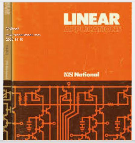 And the blue books with datasheets....took over 1 meter on the bookshelf PicomiteVGA PETSCII ROBOTS |
||||
| Paul_L Guru Joined: 03/03/2016 Location: United StatesPosts: 769 |
Boy, those books bring back memories ..... Robert Pease, Jim Williams and Bob Widlar worked for NSC and were good friends ... and all of them are long gone. Bob Pease (MIT, 1961) was the designer of the LM331 and LM337 circuits. He and I used to race more of less standard VW bugs, I had a 1953 20 Hp and he had a 1956 36 Hp. He always won. He died when he crashed his 1969 VW in 2011 after attending a memorial service for Jim Williams. Jim and the two Bobs were the guys responsible for writing all of those reference books. I have an almost complete set packed away in the attic somewhere. Who actually invented the op amp is open to question. It could have been John Ragazzini in 1947 at Bell Labs, or it could have been Clarence Lovell, Loebe Julie and George Philbrick about 1950 at Bell Labs. George Philbrick actually produced the first commercially useful op amp, the K2-W, in 1953, using two twin triode hi mu 12AX7 tubes fed with +/- 300 v.d.c. http://www.philbrickarchive.org/k2-w_refurbished.pdf Bob Pease worked for George Philbrick in the early 1960s before he hooked up with NSC. I worked for Loebe Julie in the early 1960s before I hooked up with Pan Am. The original 1961 vintage Sperry/Douglas DC-8 flight simulator used about 600 K2-W Philbrick op amps. I once told youse guys that I'm older than dirt and you didn't believe me. Paul in NY (Cornell 1959, MIT 1961) |
||||
CircuitGizmos Guru Joined: 08/09/2011 Location: United StatesPosts: 1427 |
Loved the cover of the Bob Pease book Troubleshooting Analog Circuits with the rat's nest of wires. I used to read Pease Porridge. Micromites and Maximites! - Beginning Maximite |
||||
| Paul_L Guru Joined: 03/03/2016 Location: United StatesPosts: 769 |
Well actually ..... current common op amps have an open loop gain of 10^5 to 10^8. That's right ... not a typo ... 100,000 x to 1,000,000,000 x!!! Bob was quite a character. He used to try to stop conversations and make people think. One of his favorite statements was "My favorite programming language is .... solder." Loebe Julie would tend to throw things at him after a particularly fragrant Peaseism. Paul in NY Edited 2020-11-19 15:46 by Paul_L |
||||
| Paul_L Guru Joined: 03/03/2016 Location: United StatesPosts: 769 |
Well, I'll be hornswaggled! I just found a Pease Porrige reprint from May 2, 1999 wherein Bob interviewed Loebe Julie. https://www.electronicdesign.com/technologies/analog/article/21763955/whats-all-this-julie-stuff-anyhow It seems that Loebe did the actual work for the first operational amplifier design when he was working for Professor Louis Ragazzini at Columbia University in 1941. This opamp was the heart of the M91 gun director which would routinely knock German bombers out of the air as they approached the English coast without human assistance. After the war Ragazzini took credit for the design and George Philbrick improved it, but it was all based on Loebe Julie's earlier work. I worked for Loebe Julie at Julie Research Laboratories in 1965 and 1966 and saw him daily, but he never mentioned this earlier work to me. At that time Julie Research was manufacturing a high precision resistance measuring bridge based on a Kelvin-Varley voltage divider which had a resolution of 0.1 ppm (that's 0.0001%) and an uncertainty of 2 ppm (0.002%). Loebe couldn't make it tighter because the NBS could only define resistance with a precision of 1 ppm with the Leeds & Northrup Thomas one ohm resistor standard in a temperature controlled oil bath. https://www.ebay.com/itm/LEEDS-NORTHRUP-THOMAS-1-ONE-OHM-4210-STANDARD-RESISTOR-CALIBRATOR-/273829277710 NBS also had a problem defining the volt. They used a large bank of Eppley / Weston saturated cadmium sulfate standard cells immersed in a giant temperature conroled oil bath. This was about as portable as a large bathtub and would take days to reach a stable temperature if it was moved. Loebe, as usual, had a better idea. The problem was to maintain the cells at an absolutely stable temperature somewhere above normal laboratory ambient temperature. Loebe discarded the giant oil bath in favor of a split aluminum block with a channel milled into the mating surfaces into which an standard cell could be inserted. He then surrounded this aluminum block with a two piece cast layer of foam insulation, surrounded that with another layer of plate aluminum and then surrounded that with an additional layer of foam and a nice wooden case. He now had an insulated oven within a surrounding insulated oven. The outer aluminum plate oven was heated to well above normal room ambient, about 90°F, using resistors attached to the aluminum plates and controlled by a thermistor bridge driving a variable duty cycle triac fed resistor. He could easily hold the outer oven to 90°F +/- 0.1°F while the outside room ambient varied +/- 10°F around 75°F. The inner aluminum block oven was heated by resistors to about 4°F above the temperature of trhe outer oven. The resistors were switched on or off by a mercury thermometer with wire electrodes inserted into the mercury capillary tube. The inner oven would exhibit a very low temperature rate of change due to the stable differential above the outer oven. This entire one cubic foot battery heated gadget weighed about 15 pounds and could be moved around like a tool box. The voltage output of the standard cells would be stable as long as you kept the box upright and did not jar it while moving it. Using saturated standard cells as transfer standards ended with the availability of buried zener reference circuits. Here's what Bob Pease said on the subject. https://www.electronicdesign.com/technologies/analog/article/21804689/whats-all-this-ltz1000-stuff-anyway Paul in NY |
||||
| The Back Shed's forum code is written, and hosted, in Australia. | © JAQ Software 2026 |
