
|
|
Forum Index : Microcontroller and PC projects : Well, apparently I have killed my unit.
| Author | Message | ||||
| Womble Senior Member Joined: 09/07/2020 Location: United KingdomPosts: 267 |
Yes, thats exactly what I meant. Googling the numbers: '106C', this equals a capacitance value of 10 MicroFarad. The first 2 digits are '10' and the multiplier factor is 1,000,000, so the value is 10,000,000pF or 10uF (10pF x 1,000,000= 10,000,000pF= 10uF). Remember its a polarised type  make sure you connect it the right way round. make sure you connect it the right way round.No idea what the other numbers meant ... Manufacurers Code ??? I'm sure someone more knowledgeable will chip in soon with a part recommendation. Edit: Using the BOM kindly supplied by Peter here is the details for C5 (yes its a 10uF tantalum) Datasheet Regards Womble (also an amateur at electronics) Edited 2020-10-30 01:14 by Womble |
||||
| Sasquatch Guru Joined: 08/05/2020 Location: United StatesPosts: 385 |
These are suitable replacements. ĀSorry about the focus, that's about the best my phone camera can do. ĀThe one with the "through hole" legs may be easier for a beginner to solder to the pads and is also a 16V rated part to avoid this happening again. ĀIf you PM me your address I can put a couple in the mail for you! ĀAs mentioned before, you will need to observe polarity or you will quickly fry the new part. ĀWhen in doubt "Google It" If your power brick has a clean output, you might even get away without C5 for awhile. 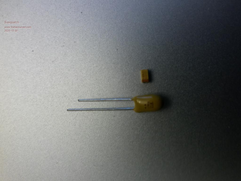 Edited 2020-10-30 01:30 by Sasquatch -Carl |
||||
| twofingers Guru Joined: 02/06/2014 Location: GermanyPosts: 1752 |
... ... where did you find this BOM? I've been looking for hours.  causality ŌēĀ correlation ŌēĀ coincidence |
||||
| Sasquatch Guru Joined: 08/05/2020 Location: United StatesPosts: 385 |
See the .zip file posted by Womble above. Edit: Here is the Orignal post: https://www.thebackshed.com/forum/ViewTopic.php?FID=16&TID=12322#149847 Edited 2020-10-30 02:04 by Sasquatch -Carl |
||||
| twofingers Guru Joined: 02/06/2014 Location: GermanyPosts: 1752 |
@Sasquatch Thanks!  I read the Wombles text before the edit.  Michael causality ŌēĀ correlation ŌēĀ coincidence |
||||
| Womble Senior Member Joined: 09/07/2020 Location: United KingdomPosts: 267 |
@TwoFingers I spend far too much time reading this forum The search function is quite good, if slow, but takes a bit of getting used to. I often specify the "author" field as "matherp" because that usually finds the Good Stuff Womble  Edited 2020-10-30 02:31 by Womble |
||||
| twofingers Guru Joined: 02/06/2014 Location: GermanyPosts: 1752 |
Thanks for finding this good stuff.  I think there is nothing wrong with finding it in more places ...! Michael causality ŌēĀ correlation ŌēĀ coincidence |
||||
TassyJim Guru Joined: 07/08/2011 Location: AustraliaPosts: 6538 |
Please measure the voltages with the USB A-A cable in place. If you can program the unit OK, the supply must be at least 4V to give enough voltage on the 3.3V side to allow programming to work. The regulator needs ~1.3V drop across it and the CPU probable will get away with 2.7V so 4V in 'should' work. I don't think that the capacitor is faulty but as it's in the same circuit, measuring the voltages with power supplied via the A socket will confirm. Faulty power supply, power supply limiting to 100mA, faulty cable, faulty B socket, faulty switch. Hopefully bad solder joint on one of the above. Jim VK7JH MMedit |
||||
| Womble Senior Member Joined: 09/07/2020 Location: United KingdomPosts: 267 |
I agree. Particularly given how quickly things get buried on the forum. You know its been posted, but you cant seem to find it. |
||||
| yock1960 Senior Member Joined: 18/08/2020 Location: United StatesPosts: 167 |
With the A-A connection, power switch off, center pin of switch to ground checks 0V. With power on checks 2.3V. Steve |
||||
| TassyJim Guru Joined: 07/08/2011 Location: AustraliaPosts: 6538 |
I find it hard to believe that you are able to program the firmware with voltages that low! That will put the CPUs supply at 1 volt. Jim VK7JH MMedit |
||||
| yock1960 Senior Member Joined: 18/08/2020 Location: United StatesPosts: 167 |
Well, I'm only going by the messages from what the software says, I really have no idea. Steve |
||||
| yock1960 Senior Member Joined: 18/08/2020 Location: United StatesPosts: 167 |
What would you consider 'clean' and what risks would I be taking if it wasn't clean enough or became unclean...as it were? Steve |
||||
| Sasquatch Guru Joined: 08/05/2020 Location: United StatesPosts: 385 |
Well it's about ripple voltage, which you would need a oscilloscope to measure. ĀI'd remove C5 and try powering the CMM2 from a computer USB port, that should provide clean power. ĀThen try a known good power brick (something that has worked with the CMM2 before). ĀRemoving the tantalum capacitor at C5 will tell you if it's just the capacitor or if the voltage regulator got toasted too. ĀIt's very difficult to try to diagnose remotely. ĀI would think anything short of a bad CPU chip would be worth repairing. ĀAs far as risk, you might see noise on the display or if the noise is bad enough it might not even boot. ĀI shouldn't think the output of power brick would be noisy enough to cause permanent damage as long as the voltage isn't too high. Edited 2020-10-30 11:01 by Sasquatch -Carl |
||||
| TassyJim Guru Joined: 07/08/2011 Location: AustraliaPosts: 6538 |
I do believe you, I just am very surprised that the CPU will operate so far below its design minimum. I am also surprised that your PC didn't complain about the excess current drawn from the USB. They usually have a resettable fuse to limit the drain. Rather than removing the capacitor, you could cut the trace on it's negative side. That would take it out of service and be easy to re-instate if that's not the problem. 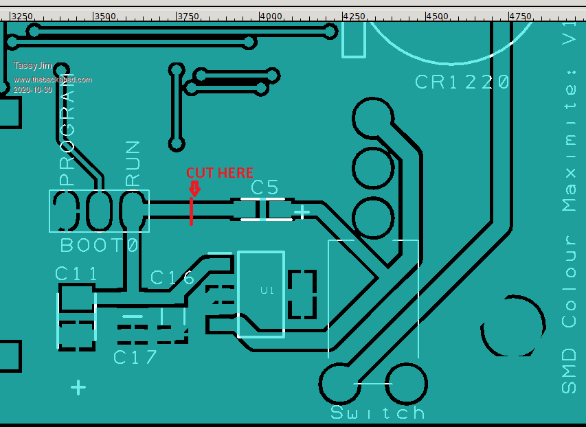 On these boards, the large areas of fill on the top side are 3.3V while the fill areas on the bottom are ground. That means it is difficult to isolate the 3.3V side of the regulator. If you cut where I have indicated, you can easily scrape off the mask either side of the cut and restore the capacitor with a blob of solder. I don't have a SMD board so I am only going by the gerber files but I think you should have room to perform the operation. Jim VK7JH MMedit |
||||
Grogster Admin Group Joined: 31/12/2012 Location: New ZealandPosts: 9975 |
Yes, those little orange-brick type caps are tantalums. Take note that the "Bar" marking on the end of a SMD tantalum, is the NEGATIVE. Many people(including me!) mistake that as the positive, and as with standard electrolytics, tantalums don't like being installed backwards - they will explode. Literally. Yes, it is 10uF, and going by the BOM, it is a 16v type NOT 6v3, so 9v should not really have killed it. Jim does not think the cap is the problem, and he may well be correct, but that is where I would start, as it is easier to remove/isolate that then the regulator. Others here have hinted at the idea the regulator could also be cooked now, and that also may be the case, but I would start with the cap. Jim's idea of cutting the PCB track is a good one, if you don't have any SMD rework station or any experience playing with SMD parts. If you cut the track and power up and the voltage is still low, then the regulator will also have to be replaced. Something is not right at the power-input side of things. The regulator should have no problem at all with 9v input. Whatever the cause, I will be interested to find out what it is, so please do keep the thread updated. Good luck.  Smoke makes things work. When the smoke gets out, it stops! |
||||
| Solar Mike Guru Joined: 08/02/2015 Location: New ZealandPosts: 1211 |
Don't think that is correct Grogs, according to the data sheets on all the solid smd tants that I have, the bar end is anode or +ve. Its only -ve on non solid electrolytic types. Cheers Mike |
||||
| yock1960 Senior Member Joined: 18/08/2020 Location: United StatesPosts: 167 |
Well, it took several passes to cut through the trace and after I finally did, I had about 30 seconds of hope, as the busy light went out after powering on...but still no display. Voltage now checks about 1.7V on the center pin. Another new development, is that when powering from the laptop to the B port, the device shows up as a com port now. Further futzing around just now shows the busy light stays on after putting the run/prog jumper back on. I installed Tera Term, set the port to 115200,8,1 and fired it up. Nothing. If I press the reset button while the terminal program is running, I get a few garbage characters back. Cube programmer still connects...doesn't complain...I did not re-re-flash. So, apparently, even though 9V should not have done this...it did...and the regulator is toast and maybe C5 and maybe...what else? This was already going to be a challenge for me to remove and replace these components....time to punt? Steve |
||||
| CaptainBoing Guru Joined: 07/09/2016 Location: United KingdomPosts: 2171 |
easy tiger! 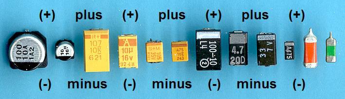 (from the many bits of paper stuck to my workshop wall... I posted without watermark so you can all take a clean copy and stick it to yours Ā )Edited 2020-10-30 19:57 by CaptainBoing |
||||
| matherp Guru Joined: 11/12/2012 Location: United KingdomPosts: 11499 |
Definitely!!! 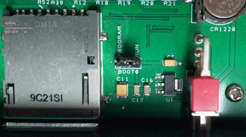 |
||||
| The Back Shed's forum code is written, and hosted, in Australia. | © JAQ Software 2026 |
