
|
|
Forum Index : Microcontroller and PC projects : Circuit advice
| Author | Message | ||||
| Turbo46 Guru Joined: 24/12/2017 Location: AustraliaPosts: 1693 |
Please do. Which one? Bill Keep safe. Live long and prosper. |
||||
lew247 Guru Joined: 23/12/2015 Location: United KingdomPosts: 1709 |
and what would the circuit look like Would a logic level mosfet not be better? |
||||
| Turbo46 Guru Joined: 24/12/2017 Location: AustraliaPosts: 1693 |
Do you have 5 volt compliant pin available? Bill Keep safe. Live long and prosper. |
||||
| Mixtel90 Guru Joined: 05/10/2019 Location: United KingdomPosts: 8911 |
>----3v3 ------------Vin � � � �Vout------>5V � � � �| � � � 100k � � � �| � � �+-------/SHDN � � � �| � � �|c � � � �| � � / >-1k---+----| NPN � � � � � � �\e � � � � � � � | --------------+-------GND With the input floating during boot or switched low the 5V supply is shut down. When you want the 5V to switch on, just raise the control pin. The /SHDN pin has an internal 100k pull-up to Vin so you can forget about it. The 1k is for stability and to give some protection to the control pin. The 100k pullup on the base passes insufficient current to damage anything if Vin gets as high as 5V. Edited 2020-11-01 08:23 by Mixtel90 Mick Zilog Inside! nascom.info for Nascom & Gemini Preliminary MMBasic docs & my PCB designs |
||||
| Turbo46 Guru Joined: 24/12/2017 Location: AustraliaPosts: 1693 |
Lower the control pin? The 1k also limits the output from the control pin to the base of the transistor. Don't make it any larger or the transistor may not turn off completely. Bill Keep safe. Live long and prosper. |
||||
| Mixtel90 Guru Joined: 05/10/2019 Location: United KingdomPosts: 8911 |
Sorry, quite correct. The 1k is fine - you'll be well under 0.6v on the base. Edited 2020-11-01 08:56 by Mixtel90 Mick Zilog Inside! nascom.info for Nascom & Gemini Preliminary MMBasic docs & my PCB designs |
||||
| panky Guru Joined: 02/10/2012 Location: AustraliaPosts: 1127 |
With the 1K resistor between the driving pin and the base, with the uMite o/p high (3.3V) you will pull 3.3mA from the base unless you have the uMite output as open collector. While this is still OK as far as the transistor is concerned, it is wasting current. If minimum current is the goal (as well as correct switching), then I think an N channel enhancement mode MOSFET is a far better way to go. Being a voltage operated device, it will drag negligible current from the uMite and its on resistance is sufficiently low to ensure pulling the Enable pin of the Buck converter effectively to ground. A suitable MOSFET would be a 2N7002. With a typical gate threshold voltage (turn on/off) of around 2.1V, the uMite can directly control this device. The other advantage of the MOSFET here is that with the uMite pin either undefined (and thus high impedence) or unconnected (even higher impedence  ), the MOSFET will be on pulling the Enable line low and holding the buck converter off. To turn the buck converter on, set the uMite pin low. When on (via the 100k resistor from gate to 3.3V, same as the 100K from base to 3.3V), the MOSFET will pull just 33uA from the Buck converter via its internal 100K pull up. ), the MOSFET will be on pulling the Enable line low and holding the buck converter off. To turn the buck converter on, set the uMite pin low. When on (via the 100k resistor from gate to 3.3V, same as the 100K from base to 3.3V), the MOSFET will pull just 33uA from the Buck converter via its internal 100K pull up.You would not need the 1K series resistor. Doug. ... almost all of the Maximites, the MicromMites, the MM Extremes, the ArmMites, the PicoMite and loving it! |
||||
| lew247 Guru Joined: 23/12/2015 Location: United KingdomPosts: 1709 |
I've just realised something from reading the instructions for the boost converter I want to use The /SHDN pin is pulled low ie less than 0.4V to turn the boost converter on BUT it's internally connected via a 100K resistor to +V �so only needs grounding to turn on Could I just connect the /SHDN pin direct to a MM pin with a 10K resistor to ground? I'm not switching any current as such, only grounding a pin or floating it I "think" that should work, as the /SHDN pin only need to be either pulled to ground or left "floating" to switch the unit on and off, it doesn't need to supply or switch 3.3V Edited 2020-11-01 19:09 by lew247 |
||||
| Mixtel90 Guru Joined: 05/10/2019 Location: United KingdomPosts: 8911 |
Yep, that should be fine (oddly enough I came to the same conclusion last night after I'd gone to bed!). With /SHDN floating and 10k it would float to about 0.3V so the converter should shut down though. With 3.3v in you need at least 1.2V on /SHDN to run the converter. Try 120k pulldown to get 1.8V or even omit the pulldown altogether. Now, as you say, just pull /SHDN down to switch it off or float it to switch it on. The only reason to use an active device to pull /SHDN down is to get below that 0.4V point. If the output pin is capable of that at the very low current needed (33uA I think) then direct connection will work. Edited 2020-11-01 22:05 by Mixtel90 Mick Zilog Inside! nascom.info for Nascom & Gemini Preliminary MMBasic docs & my PCB designs |
||||
| lizby Guru Joined: 17/05/2016 Location: United StatesPosts: 3784 |
I don't know what the output of the converter looks like (for testing the result), but could this not be tested with a simple pushbutton switch to 0V? When pressed, it goes on, when released, off? If so, output low on the MM should turn on, and high or tri-state should turn off. PicoMite, Armmite F4, SensorKits, MMBasic Hardware, Games, etc. on FOTS |
||||
| Mixtel90 Guru Joined: 05/10/2019 Location: United KingdomPosts: 8911 |
It works the other way round - low to shut down, high or tri-state to turn on. I fell into that trap at first. :) Yes, it could be tested with a button or a simple link to ground. The limits with a 3.3v input are <0.4V to turn off, >1.2V to switch on. Output from the boost converter is +5V. Edited 2020-11-01 23:48 by Mixtel90 Mick Zilog Inside! nascom.info for Nascom & Gemini Preliminary MMBasic docs & my PCB designs |
||||
| lew247 Guru Joined: 23/12/2015 Location: United KingdomPosts: 1709 |
I'm happy connecting it directly to the MM pin but if I do This (pin 13 as an example of use not the exact pin I'll be using) SETPIN D13, DOUT PIN(D13) = 0 pause 5000 do whatever the program needs to do with the converter turned on then SETPIN D13, OFF Sleep for however long... wake up SETPIN D13, DOUT PIN(D13) = 0 do whatever the program needs to do with the converter turned on then SETPIN D13, OFF and repeat... I'm not sure if that will work or if it will work with Armmite What I want to do is have the pin float and not go high or low when not used Edited 2020-11-02 01:11 by lew247 |
||||
| Mixtel90 Guru Joined: 05/10/2019 Location: United KingdomPosts: 8911 |
Isn't that what Setpin Off is for? You should be able to just use pin(d13)=0 setpin d13 dout to start off with the 5V turned off once at the beginning then turn the 5V on and off with setpin d13 off to switch it on setpin d13 dout to switch it off I've not tried this. Is there an LED from 3.3 to D13 on the Armmite? If not, test it with one. On PIC chips the data latch comes first, followed by the output driver. With the driver turned off the output floats. If the latch is set low then the driver will switch the output between float and low. Mick Zilog Inside! nascom.info for Nascom & Gemini Preliminary MMBasic docs & my PCB designs |
||||
| lew247 Guru Joined: 23/12/2015 Location: United KingdomPosts: 1709 |
On a STM32L431CCT6 "48 pin Armmite" unprogrammed Can I use "The Microbridge" to connect usb from the computer to pins 12 CONSOLE_TX A2 13 CONSOLE_RX A3 and then program it by dropping the bin file from the PC, or do I have to have one of those STM links to program this chip? It won't be on a development board |
||||
| Mixtel90 Guru Joined: 05/10/2019 Location: United KingdomPosts: 8911 |
The microbridge has 2 sets of TTL signals, one pair to the console pins and the others to the ICSP pins. The USB connection to it is switched between the two. Normally it converts the USB to TTL serial on the console pins. In programming mode it acts like a PICkit programmer and can be used to install or change the firmware on the main chip via ICSP. You can't install or modify the firmware (MMBasic) via the console pins. You can change the BASIC program in this way though. I've never seen or used the Armmite so I've no idea how it works, but I suspect you'll have to either use STM or patch the signals from the microbridge onto it somehow. The microbridge needs /MCLR, PGM, PGD and ground (plus power to everything, of course). /MCLR needs at least a resistor to the supply - it can't be directly connected. Edited 2020-11-03 08:41 by Mixtel90 Mick Zilog Inside! nascom.info for Nascom & Gemini Preliminary MMBasic docs & my PCB designs |
||||
| lizby Guru Joined: 17/05/2016 Location: United StatesPosts: 3784 |
Re STM32L431CCT6, from this thread 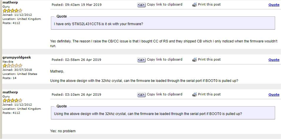 Now this doesn't specifically say "microbridge", and I haven't used this particular L4 (just the Nucleos), but it seems worth a try. One caveat--you're not likely to get much help with this module. ~ Edited 2020-11-03 09:11 by lizby PicoMite, Armmite F4, SensorKits, MMBasic Hardware, Games, etc. on FOTS |
||||
| JohnS Guru Joined: 18/11/2011 Location: United KingdomPosts: 4335 |
ICSP is for PIC32, not for STM32. The STM32 family has multiple ways of being programmed (bigger, newer parts have more options). John |
||||
| Mixtel90 Guru Joined: 05/10/2019 Location: United KingdomPosts: 8911 |
Ah, right. Thanks lizby & John. As I said, I'm not familiar with the Armmite. I thought it was fundamentally the same as a PIC-based device. Sorry if I misled you, lew247, I don't think I've been of much help there. :( Mick Zilog Inside! nascom.info for Nascom & Gemini Preliminary MMBasic docs & my PCB designs |
||||
| The Back Shed's forum code is written, and hosted, in Australia. | © JAQ Software 2026 |
