
|
|
Forum Index : Microcontroller and PC projects : ArmmiteF4 firmware: V5.06.00
| Author | Message | ||||
disco4now Guru Joined: 18/12/2014 Location: AustraliaPosts: 1127 |
Ok, I have not use OPTION LCDPANEL CONSOLE before but here are some images on the 800*480 OTM8009A I have working. 3.97" is the claimed size. Using font 2 about 25 lines 66 cols. Quite usable I think. Issue at present where cursor does'nt down arrow past 3rd last line. 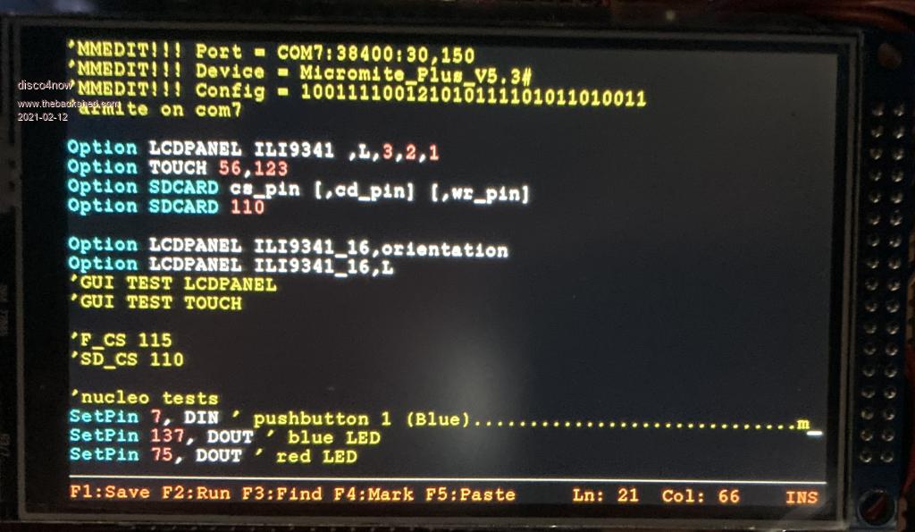 using Font 1 about 37 lines 100 cols I think you could use this as well I think, though a little small. Issue at present where cursor does not down arrow past 3rd last line. 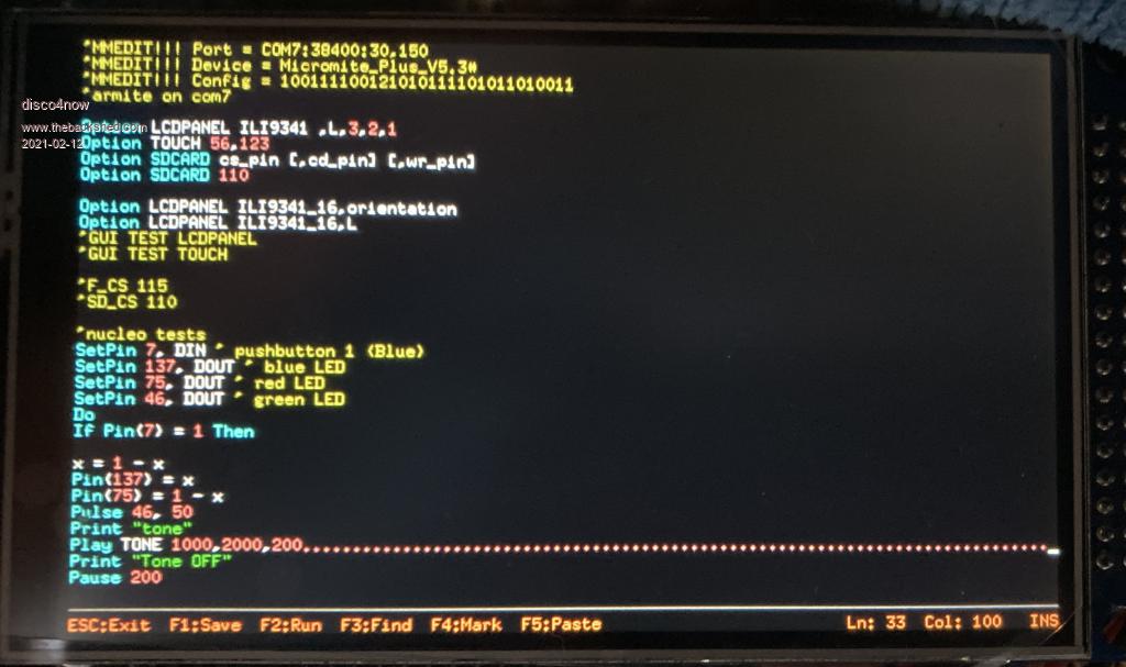 using font 7 48 lines 133 cols This is pretty small,nearly too small to read, but with a magnifier is still very clear. You probably would not use this. Does allow cursor to last line. 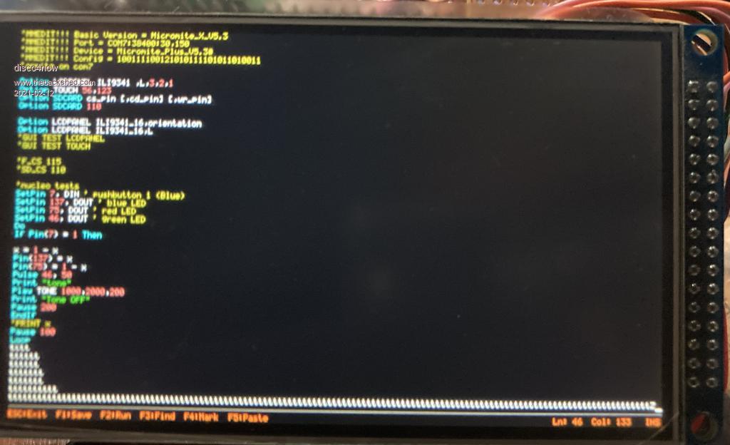 This one is not really blurred, the phone must have moved, but the font is small. Regards Gerry Edited 2021-02-12 14:20 by disco4now F4 H7FotSF4xGT |
||||
| phil99 Guru Joined: 11/02/2018 Location: AustraliaPosts: 3291 |
It seems everyone has their own favorite LCD screen, so is it practical to write the drivers as Library Functions instead of compiling them into MMBasic? |
||||
| lizby Guru Joined: 17/05/2016 Location: United StatesPosts: 3784 |
Garry--Font one looks excellent with that LCD for making up a MMBasic computer. It's not so much their favorite, as what is Peter willing to implement on the F4 (which doesn't provide for loadable drivers)? Or, if he is willing, what is the best choice? I'd prefer the 16-bit 17x2 form to the Arduino footprint, since a small adaptor should be easy. Then, if desired, a backpack which brought out keyboard, ESP-01 connector, sound, and the pi-type 20x2 header would not be difficult. I don't have a strong preference between 480x320 (the minimum) and 800x480, but for $2US more, why not go for the slightly larger and sharper LCD? One possible question is the long-term availability of these LCDs. If it's a doodle, more or less, because for the 480x320 SPI ILI9488 there's already a "loadable driver" with the MMX platform, I'd still like to see it implemented--provided more than one additional LCD driver can be provided. Scrolling in the editor would be a test of its speed. But if only one can be added, the ones Garry pointed out appear better. PicoMite, Armmite F4, SensorKits, MMBasic Hardware, Games, etc. on FOTS |
||||
Chopperp Guru Joined: 03/01/2018 Location: AustraliaPosts: 1126 |
Updated a number of F4's last night. Most of them played ball OK apart from the odd USB connection issues. Unfortunately, the Serial only one (U/S USB) was non responsive to the STM programmer with the UART connection (after eventually getting the UART mode going on a good F4). I thought I had another one with a faulty USB interface, but I couldn't find it. May have come good. I did try the serial console mode OK on a good one. I did note from reading the table on the back of the board that the jumper shunt from BT1 to GND can be left in situ in Flash mode. (X - Don't care). May save losing the bugger. Brian ChopperP |
||||
| lizby Guru Joined: 17/05/2016 Location: United StatesPosts: 3784 |
Regarding the 480x320 SPI ILI9488 on the F4, any recommendation other than these pins? CS-33, D/C-87, RESET-97, LED-96, T_CS-72, T_IRQ-67 And SPI2 should be used? Edited 2021-02-13 01:45 by lizby PicoMite, Armmite F4, SensorKits, MMBasic Hardware, Games, etc. on FOTS |
||||
| disco4now Guru Joined: 18/12/2014 Location: AustraliaPosts: 1127 |
Did holding Key 0 down during a restart cause it to start with the console on the serial port. Does not seem to work for me. F4 H7FotSF4xGT |
||||
| Chopperp Guru Joined: 03/01/2018 Location: AustraliaPosts: 1126 |
Key 0 on the F4 board worked for me. Very small push button. Brian ChopperP |
||||
| lizby Guru Joined: 17/05/2016 Location: United StatesPosts: 3784 |
Garry--do you have handy a mapping of the 32-pin to 34-pin adaptor? I plan to send off an order to JLCPCB within the next few days, and would add the adaptor if I can whip it up. PicoMite, Armmite F4, SensorKits, MMBasic Hardware, Games, etc. on FOTS |
||||
| disco4now Guru Joined: 18/12/2014 Location: AustraliaPosts: 1127 |
Sorry only got it on paper.its like this. Screen This Side of Pins ------------------------------------------------------------------------- | The 32 Pins on the Armmite board looking from the top. | | | 3.3 N/C PEN-IRQ MOSI TCLK DC RD B1 B3 B5 B7 B9 B11 B13 B15 GND | GND GND LCD-BL MISO T-CS CS WR B0 B2 B4 B6 B8 B10 B12 B14 RST | | | The 34 pin connector that will take the LCD. looking from top. | |T-CS PEN MISO GND VCC BL B15 B13 B11 B9 B7 B5 B3 B1 RST WR CS |CLK N/C MOSI N/C GND VCC N/C B14 B12 B10 B8 B6 B4 B2 B0 RD RS -------------------------------------------------------------------------- staight mapping for B0-B15, GND, WR,RD, CS, RST, T-CS, MOSI, MOSI CLK to TCLK BL to LCD-BL RS to DC PEN to PEN-IRQ 3.3 to VCC The only thing to consider would be if some LCDs are nor logic driven on the BL pin, then might need a option to either connect to LCD-BL ot to 3.3v The ones I looked at use BL to switch a transistor, so logic level connect to LCD-BL is OK. F4 H7FotSF4xGT |
||||
| lizby Guru Joined: 17/05/2016 Location: United StatesPosts: 3784 |
Thank you very much, Garry. That clears up the questions I had about the meaning on the TFT schematic in the F4 PDF of NOE, NWE, A18 and NE1 as WR, WD, CS, D/C. PicoMite, Armmite F4, SensorKits, MMBasic Hardware, Games, etc. on FOTS |
||||
| disco4now Guru Joined: 18/12/2014 Location: AustraliaPosts: 1127 |
Correct, NOE, NWE, A18 and NE1 are WR, RD, CS, D/C. , but could not see that new WD pin (typo I think) Regards Gerry F4 H7FotSF4xGT |
||||
| lizby Guru Joined: 17/05/2016 Location: United StatesPosts: 3784 |
Well, here's my first pass at a PCB for an "Armmite F4 MMBasic computer", with ILI9488 SPI TFT LCD display, ESP-01, keyboard connector, and pi-type 20x2 connector, sent yesterday to JLCPCB (slow boat, since express plus customs handling adds about $30 where I am). I say "first past" because I doubt I got it all right. 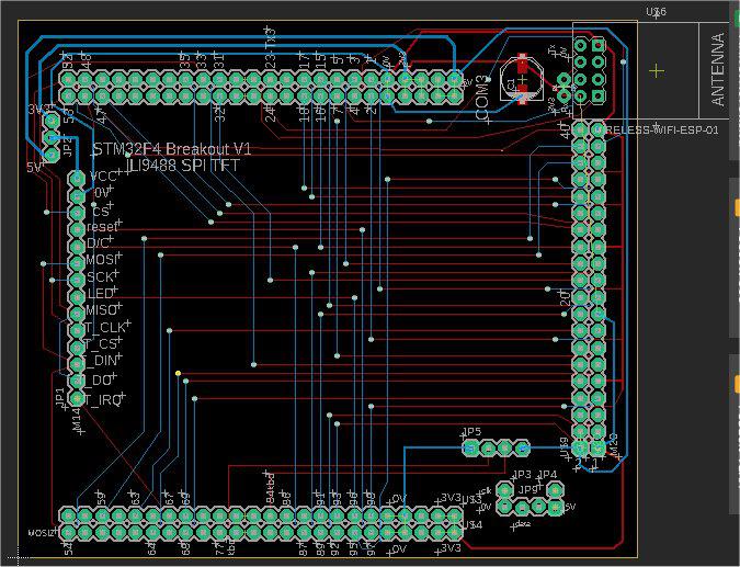 The schematic is an embarrassment. I didn't have an F4 footprint, and I've never succeeded in creating a new EagleCad part, so I used 4 24x1 headers. I didn't know the pin designation for the keyboard so I placed a 4-pin header near the footprint with 5V,0V,kbd-data and kbd-clock. I'll solder links when the boards arrive, then fix and resubmit with other corrections. I did use this F4 footprint on a different PCB, so I know it works. 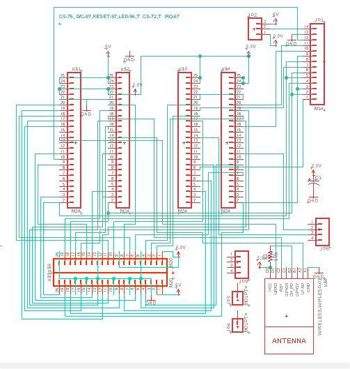 For the LCD control (on SPI2), I used the following pins: CS-33, D/C-87,RESET-97,LED-96,T_CS-51,T_IRQ-67 Here's the 40-pin header layout--orientation as on the CMM2, with pin1 on the lower left. 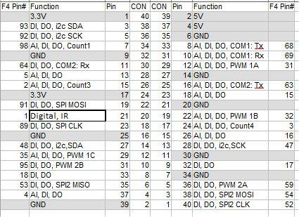 And F4 board pin usage: 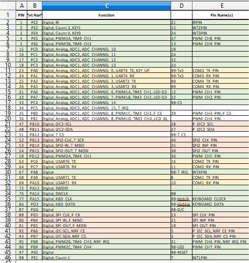 One possible issue--SPI MISO (pin 90, PB4) is not among the pins on the F4 24x2x2 headers, so there is no complete SPI(1) port on the 40-pin (20x2) connector. Regarding layout, I put the SPI LCD header inboard of the 16x2 16-bit LCD header on the F4 board so that the original 320x240 LCD could be used with this breakout board, or others using an adaptor with the 16x2 header. I hope this will work toward making a relatively inexpensive F4 "MMBasic computer" available. PicoMite, Armmite F4, SensorKits, MMBasic Hardware, Games, etc. on FOTS |
||||
| matherp Guru Joined: 11/12/2012 Location: United KingdomPosts: 11513 |
I could change the pinout to PA6. This would mean losing one channel of PWM1 outputs. e.e. PWM1A, PWM1B, PWM1C but no PWM1D Thoughts? |
||||
| lizby Guru Joined: 17/05/2016 Location: United StatesPosts: 3784 |
Can you explain this further? There already is no PWM 1D on the 40-pin connector. Would then PA6 (pin 31, Digital, Analog, ADC1, ADC_CHANNEL_6, PWM1A, TIM3_CH1, LED-D2) go to pin 21 (MSBasic numbering) which for a pi is SPI(1) MISO)? Is something to be done with PB1 (pin 36, Digital, Analog, ADC1, ADC_CHANNEL_8, PWM1D, TIM3_CH4, LCD_BL)? (Which I now notice should probably be LCD_BL instead of PB9.) Does this allow firmware configuration of SPI MISO depending on an LCD option setting? I'm happy to consider any recommendations/suggestions for a version 2 PCB. I forgot about breaking out sound (how?), and would probably bring out IR to a separate header, but I've never used it and don't know what considerations to take into account. ~ Edited 2021-02-16 01:04 by lizby PicoMite, Armmite F4, SensorKits, MMBasic Hardware, Games, etc. on FOTS |
||||
| matherp Guru Joined: 11/12/2012 Location: United KingdomPosts: 11513 |
Sorry - looking too quick PB1 is and will remain the backlight and is not directly available to MMbasic If I make the change the numbering won't change just PA6 becomes SPI-MISO. This will be fixed. PWM1 will end up with just 1A and 1B A SPI TFT always uses the same SPI pins as the touch controller on the TFT header |
||||
| lizby Guru Joined: 17/05/2016 Location: United StatesPosts: 3784 |
Ok, got it, I think. 1. PB1 will be LCD_BL (instead of the PB9 which I now have). 2. PA6 will become SPI-MISO (and will connect to pin 21 on the 40-pin pi-header). 3. ? PB0 (currently PWM1C) will become PWM1A? Or only PWM1B and PWM1C will be available? PicoMite, Armmite F4, SensorKits, MMBasic Hardware, Games, etc. on FOTS |
||||
| matherp Guru Joined: 11/12/2012 Location: United KingdomPosts: 11513 |
PWM1B will become PWM1A, PWM1C will become PWM1B - no other PWM1 The backlight PWM is completely separate and just runs continuously. The only issue with it is whether ON is 3.3V or 0V and different displays need a different answer. I may need to do a firmware tweak for this. Edited 2021-02-16 03:10 by matherp |
||||
| disco4now Guru Joined: 18/12/2014 Location: AustraliaPosts: 1127 |
I think this will have an effect on accessing the windbond flash chip and NRF socket via SPI. PA6 also has the D2 LED to 3.3v via a 510 ohm resistor. Not sure what this would do to SPI.  Could it be left as is and then design the backpack board to have a pin placed in the correct spot and pick up MISO off the NRF socket. Gerry Edited 2021-02-19 10:28 by disco4now F4 H7FotSF4xGT |
||||
| lizby Guru Joined: 17/05/2016 Location: United StatesPosts: 3784 |
Garry--that would work for me. As I see it, SPI MISO is the lower right female header position on the NRF24L01 socket (if the USB connector is up), 1/2 inch in from the lower right 5V pin (5x.1" in). As a matter of interest, when you compiled MMBasic with the driver for the 800*480 OTM8009A, how much free flash did you have before and after? PicoMite, Armmite F4, SensorKits, MMBasic Hardware, Games, etc. on FOTS |
||||
| disco4now Guru Joined: 18/12/2014 Location: AustraliaPosts: 1127 |
Yes that is where MISO seems to be. looking underneath you can see the track go off toward the JTag-3 connector. I don't think the OTM8009A made any significant difference to the flash available, stilled showed 144K. Regards Gerry F4 H7FotSF4xGT |
||||
| The Back Shed's forum code is written, and hosted, in Australia. | © JAQ Software 2026 |
