
|
|
Forum Index : Microcontroller and PC projects : better measurements by a running mean
| Author | Message | ||||
| Mixtel90 Guru Joined: 05/10/2019 Location: United KingdomPosts: 8904 |
Apparently there is a problem with some capacitors formed on the die that are the wrong value. It wasn't considered to be important enough to redo the design, although there may be a correction if there are later releases. Mick Zilog Inside! nascom.info for Nascom & Gemini Preliminary MMBasic docs & my PCB designs |
||||
| Volhout Guru Joined: 05/03/2018 Location: NetherlandsPosts: 5930 |
The difference between the running mean and John's algorythm is that the running mean first output value is the measured value. And it increases in accuracy. John's algorythm outputs 1/n measured value as a first value, and after n iterations it is ramped up to the filtered value. Some benefit for each method. PicomiteVGA PETSCII ROBOTS |
||||
| andreas Senior Member Joined: 07/12/2020 Location: GermanyPosts: 226 |
Yes - exactly. I did some comparison and found these values: n Pin(temp) running mean ewma ---------------------------------------------------- 1 18.60978475 18.60978475 17.76693208 2 18.60978475 18.60978475 17.85121735 3 18.60978475 18.60978475 17.92707409 4 17.67328178 18.37565901 17.90169486 5 18.60978475 18.42248416 17.97250385 6 17.67328178 18.2976171 17.94258164 7 18.14153327 18.27531941 17.9624768 8 18.60978475 18.31712758 18.0272076 9 18.60978475 18.34964504 18.08546531 10 17.67328178 18.28200871 18.04424696 10 18.14153327 18.26796117 18.05397559 10 17.67328178 18.20849323 18.01590621 10 18.60978475 18.24862238 18.07529406 10 18.14153327 18.23791347 18.08191799 10 18.60978475 18.2751006 18.13470466 10 18.60978475 18.30856901 18.18221267 10 18.60978475 18.33869059 18.22496988 and here is the program which calculates both methods: > list ' running mean - get better measurements Dim M As float = 0.0 ' running mean Dim ewma As float Dim n As integer = 0 ' counter [0..Max] Const Length = 10 ' up to 'Length' values are counting Const weight = 0.1 ' weight of the new measurement Print " n"," Pin(temp)"," running mean"," ewma" Print "----------------------------------------------------" ewma = Pin(temp) While true do t = Pin(temp) n = Min(Length, n + 1) M = M + (t - M ) / n ewma = (1 - weight) * ewma + weight * t Print n,t,M,ewma Pause 1000 Loop -andreas |
||||
| JohnS Guru Joined: 18/11/2011 Location: United KingdomPosts: 4335 |
That looks wrong. John |
||||
| andreas Senior Member Joined: 07/12/2020 Location: GermanyPosts: 226 |
Yes. The first value of Johns ewma is an initial measurement but this value is not printed, it is for initialization only. The second value is 90% of the first value and 10% of the new measuremnt added to the first value, iff weight = 0.1 . This process continues, 10% of every new value is added to 90% of the last sum. I think the running mean is more accurate during startup (the first 10 values), in the long run both algos seem to be equal. The bigger problem is that the Pin(temp) is jumping 1 degree between two measurements, so it can be used as a random number generator ;-) -andreas |
||||
| JohnS Guru Joined: 18/11/2011 Location: United KingdomPosts: 4335 |
Something odd in the values printed - looks like the initial Pin(temp) was oddly low. The chip bug? John |
||||
| andreas Senior Member Joined: 07/12/2020 Location: GermanyPosts: 226 |
Something odd in the values printed - looks like the initial Pin(temp) was oddly low. The chip bug? It looks like the first value was around 17.76 If have some picos here and will do some tests with them.  -andreas Edited 2021-12-19 02:26 by andreas |
||||
| andreas Senior Member Joined: 07/12/2020 Location: GermanyPosts: 226 |
Now I have tested 5 different Picos, all processed the same way: 1. Cleared the flash: Clear_flash.uf2 2. Installed Picomite: PicoMiteV5.07.02b1.uf2 3. Started minicom 2.7.1 (my host = debian linux) 4. Started: XMODEM RECEIVE on the pico and pressed Ctrl A+S to start a transfer 5. Selected: Upload xmodem 6. Selected the "running mean.bas" and started it after transfer to the pico The results are here  : :Pico#2 n Pin(temp) running mean ewma ---------------------------------------------------- 1 25.16530554 25.16530554 25.16530554 2 25.16530554 25.16530554 25.16530554 3 25.16530554 25.16530554 25.16530554 4 25.16530554 25.16530554 25.16530554 5 24.69705406 25.07165525 25.1184804 6 24.69705406 25.00922172 25.07633776 7 24.69705406 24.96462634 25.03840939 8 24.69705406 24.9311798 25.00427386 9 25.16530554 24.95719377 25.02037703 10 24.69705406 24.9311798 24.98804473 Pico#3 n Pin(temp) running mean ewma ---------------------------------------------------- 1 19.07803624 19.07803624 16.97090456 2 19.07803624 19.07803624 17.18161772 3 19.07803624 19.07803624 17.37125958 4 19.54628772 19.19509911 17.58876239 5 19.07803624 19.17168654 17.73768977 6 19.07803624 19.15607815 17.87172442 7 19.07803624 19.14492931 17.9923556 8 19.07803624 19.13656767 18.10092367 9 19.07803624 19.13006418 18.19863492 10 20.01453921 19.21851168 18.38022535 Pico#4 n Pin(temp) running mean ewma ---------------------------------------------------- 1 20.48279069 20.48279069 17.95423267 2 20.01453921 20.24866495 18.16026333 3 20.48279069 20.32670687 18.39251606 4 20.48279069 20.36572782 18.60154353 5 20.01453921 20.2954901 18.7428431 6 20.48279069 20.32670687 18.91683786 7 20.01453921 20.28211149 19.02660799 8 20.01453921 20.24866495 19.12540111 9 20.01453921 20.22265098 19.21431492 10 20.48279069 20.24866495 19.3411625 Pico#5 n Pin(temp) running mean ewma ---------------------------------------------------- 1 16.73677881 16.73677881 15.05107347 2 17.2050303 16.97090456 15.26646915 3 16.73677881 16.89286264 15.41350012 4 17.2050303 16.97090456 15.59265313 5 16.73677881 16.92407941 15.7070657 6 16.73677881 16.89286264 15.81003701 7 16.73677881 16.87056495 15.90271119 8 16.73677881 16.85384168 15.98611796 9 16.73677881 16.8408347 16.06118404 10 16.73677881 16.83042911 16.12874352 So the temperature could be anything between 16 and 25 degrees. The ewma starts often with lower values but not everytime. -andreas |
||||
| Mixtel90 Guru Joined: 05/10/2019 Location: United KingdomPosts: 8904 |
Is the ADC for temp being initialised correctly? If only one channel is to be used it will be on GP26, if two then GP26 and GP27 etc. You might be reading a floating input. See PicoMite manual page 74. Mick Zilog Inside! nascom.info for Nascom & Gemini Preliminary MMBasic docs & my PCB designs |
||||
| matherp Guru Joined: 11/12/2012 Location: United KingdomPosts: 11499 |
The temperature is on a different ADC channel from the other inputs. These internal temperature measures are always pretty ropey |
||||
| Mixtel90 Guru Joined: 05/10/2019 Location: United KingdomPosts: 8904 |
Ah... That makes sense. :) It's always worth considering a 3v reference diode if there's any intention of using the ADC inputs for measurement anyway. That's why I've been leaving space for one on my boards whether it's needed or not. An LM4040 or NFC301 3V reference can be found for 90p or less. Mick Zilog Inside! nascom.info for Nascom & Gemini Preliminary MMBasic docs & my PCB designs |
||||
| andreas Senior Member Joined: 07/12/2020 Location: GermanyPosts: 226 |
Ok, that is very interesting - thank you! What I did was simply connecting a USB cable between Pico and PC. The PC was the source of power. The picos were without any other connection and all connected to the same USB port at the same PC. Because its late here in germany I will go to bed now, but will take an external voltage for testing tomorrow. I have a WANPTEK NPS306W as power source and a RIGOL 1102Z oscilloscope for monitoring. best regards and good night ;-) -andreas |
||||
| andreas Senior Member Joined: 07/12/2020 Location: GermanyPosts: 226 |
I used the internal temperatur measured by 'Pin(temp)' in Picomite. -andreas |
||||
| Mixtel90 Guru Joined: 05/10/2019 Location: United KingdomPosts: 8904 |
If you ground 3V3EN to shut down the SMPS and power the 3V3 rail directly (at 3.3v of course!) from a stable supply the readings should (in theory) be closer. :) I'd missed the bit about Pin(temp) using a different ADC channel, sorry. Mick Zilog Inside! nascom.info for Nascom & Gemini Preliminary MMBasic docs & my PCB designs |
||||
| vegipete Guru Joined: 29/01/2013 Location: CanadaPosts: 1179 |
Since everyone likes pictures, here's a version for the CMM2, filtering a noisy square wave. 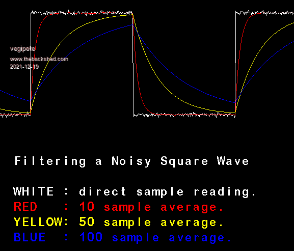 ' Filter Test for CMM2 ' written by Vegipete ' ' Uses running mean algorithm presented by Andreas cls ' use following to plot a gaussian-ish distribution 'dim hist(400) 'for i = 1 to 100000 ' reading = int(RandGauss(32) * 400) ' inc hist(reading) ' line reading+200,579,reading+200,max(0,579-hist(reading)/4) 'next i 'end text 50,400,"Filtering a Noisy Square Wave",,3 text 50,460,"WHITE : direct sample reading.",,3,,rgb(WHITE) text 50,490,"RED : 10 sample average.",,3,,rgb(RED) text 50,520,"YELLOW: 50 sample average.",,3,,rgb(YELLOW) text 50,550,"BLUE : 100 sample average.",,3,,rgb(BLUE) count = 0 square = 100 old_reading = RandGauss(32) * 40 + square old_ave_10 = old_reading old_ave_50 = old_reading old_ave_100 = old_reading average_10 = old_reading average_50 = old_reading average_100 = old_reading do ' get new reading reading = RandGauss(32) * 40 + square ' calculate new averages inc average_10, (reading - average_10 ) / 10 inc average_50, (reading - average_50 ) / 50 inc average_100, (reading - average_100) / 100 blit 1,50,0,50,MM.HRES-1,300 ' roll to the left line MM.HRES-1,0,MM.HRES-1,MM.VRES-1,1,rgb(BLACK) ' clear ' plot graph line 798,old_reading,799,reading,1,rgb(WHITE) : old_reading = reading line 798,old_ave_10, 799,average_10,1,rgb(RED) : old_ave_10 = average_10 line 798,old_ave_50, 799,average_50,1,rgb(YELLOW) : old_ave_50 = average_50 line 798,old_ave_100,799,average_100,1,rgb(BLUE) : old_ave_100 = average_100 inc count ' generate square wave if count > 200 then count = 0 square = 100 + (square = 100) * 200 endif loop function RandGauss(samples as integer) as float local i,s for i = 1 to max(samples,4) inc s,rnd next i RandGauss = s / max(samples,4) end function Visit Vegipete's *Mite Library for cool programs. |
||||
| CaptainBoing Guru Joined: 07/09/2016 Location: United KingdomPosts: 2171 |
very nice |
||||
| JohnS Guru Joined: 18/11/2011 Location: United KingdomPosts: 4335 |
andreas, Thanks for those tests! John |
||||
| andreas Senior Member Joined: 07/12/2020 Location: GermanyPosts: 226 |
Hello, thank you for all the good tips! Today I looked at VBUS the power from the USB cable comming from the PC which powers the pico. Peter told me that "You would see a change in temperature of over 4C for a small 1% change in reference voltage". I can see that the VBUS is not only changing by 1% but by 8.8% (440mV). The hihgest voltage is 5.24V and the lowest 4.80V. This explains all the problems I have with pin(temp) if it is based on this power supply. Lesson learned: A computer is not a good voltage reference when doing measurements! So the solution seems to be to get a reliable, stable power source (possibly by battery?), before doing any measuremnts. 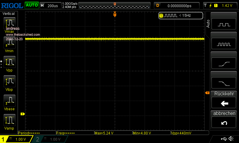 -andreas |
||||
| Mixtel90 Guru Joined: 05/10/2019 Location: United KingdomPosts: 8904 |
VBUS is the 5v supply from the USB. The reference voltage for the ADC is taken from the 3V3 line, fed from the SMPS. Because of the SMPS variation on VBUS or VSYS makes very little difference to the ADC reference. Schematic There is some filtering via C13 but variation on 3V3 still gets through. Have a look at the signal on VREF. Mick Zilog Inside! nascom.info for Nascom & Gemini Preliminary MMBasic docs & my PCB designs |
||||
| andreas Senior Member Joined: 07/12/2020 Location: GermanyPosts: 226 |
Do you mean pin 35? I suppose this is a test point or output, but not an input for an external poser supply, correct? Or does "an be used with an external reference" mean that I put in some external power supply? Btw. my external power supply has a "ripple" of some 80-120 mV (mostly 80 mV). But I have some MCP1700 3.3V power regulators here, which I could use together with an 10uF elko to create a 3.3V reference. -andreas |
||||
| The Back Shed's forum code is written, and hosted, in Australia. | © JAQ Software 2026 |
