
|
|
Forum Index : Microcontroller and PC projects : PicoMite VGA Edition - pcbs etc.
| Author | Message | ||||
| matherp Guru Joined: 11/12/2012 Location: United KingdomPosts: 11499 |
Here are the gerbers - hopefully OK as I've just ordered 5 boards from JLC PicoMiteVGA.zip Ignore the filenames - they are the right ones |
||||
| Mixtel90 Guru Joined: 05/10/2019 Location: United KingdomPosts: 8904 |
I've put 5 boards on order too. The design passed the "probe" test in SL6 so it probably (hopefully) isn't a mile out. :) My little V cutters have turned up too. Some fun to be had with those and a Dremel ... Mick Zilog Inside! nascom.info for Nascom & Gemini Preliminary MMBasic docs & my PCB designs |
||||
Grogster Admin Group Joined: 31/12/2012 Location: New ZealandPosts: 9975 |
Peter - your schematic and gerbers don't match. Schematic says 78xx reg for IC1, but gerbers say TC1264. Gerbers show IC2, schematic has no IC2 at all. Can you please post an updated schematic or better yet, a BOM for your board? I have also ordered five PCB's. No offense Mick - I still have a heap of unused CMM2 cases, so I can use one of those as Peter's board is designed to fit those cases. I might still get your one, but I don't have any matching cases, so I would have to get some. Smoke makes things work. When the smoke gets out, it stops! |
||||
| Mixtel90 Guru Joined: 05/10/2019 Location: United KingdomPosts: 8904 |
No problem, Grogster, I'm getting my boards because I already have the case that I got for measuring. :) Mick Zilog Inside! nascom.info for Nascom & Gemini Preliminary MMBasic docs & my PCB designs |
||||
| matherp Guru Joined: 11/12/2012 Location: United KingdomPosts: 11499 |
updated schematic VGAMite - Project.pdf Note SDcard holes are probably too far from the card edge as I don't yet have a module to measure. Will update in V1.1. Suggest you wait a few days until I post V1.1 before getting any made. LM4040 is optional - see Pico module datasheet missing from silkscreen - will add "OPTION SDCARD GP13,GP10,GP11,GP12" and other configuration data Will also add audio filter in V1.1 to be populated if the user requires 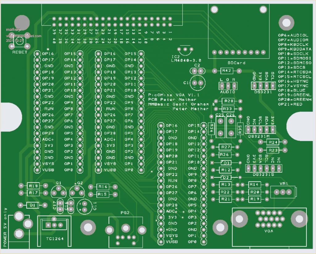 Edited 2021-12-21 20:20 by matherp |
||||
| Mixtel90 Guru Joined: 05/10/2019 Location: United KingdomPosts: 8904 |
BEEP BEEP!!!! ERROR!!!! Don't use my Gerbers directly - I screwed up on the PS/2 socket so my board needs a mod. Mick Zilog Inside! nascom.info for Nascom & Gemini Preliminary MMBasic docs & my PCB designs |
||||
| Grogster Admin Group Joined: 31/12/2012 Location: New ZealandPosts: 9975 |
Peter - can you please link me to the SD card module you are using? I think I saw it posted in another thread, but I am having trouble finding the thread and post. EDIT: Any alternatives for Q1 and Q2? Element14 don't know about BST72A's, neither does RS components. Mouser DOES know about this MOSFET, but they are out of stock and list the device as obsolete... Edited 2021-12-22 14:46 by Grogster Smoke makes things work. When the smoke gets out, it stops! |
||||
| Turbo46 Guru Joined: 24/12/2017 Location: AustraliaPosts: 1693 |
Maybe the one he provided a link to earlier? The supply pins are in the right place. sd card breakout Bill Keep safe. Live long and prosper. |
||||
| phil99 Guru Joined: 11/02/2018 Location: AustraliaPosts: 3289 |
The one Peter used on the breadboard at the beginning of the PicoMite story was brilliant and free! Glue it onto a scrap of Veroboard and the footprint can be almost anything you want for your layout. https://www.thebackshed.com/forum/uploads/matherp/2021-05-23_032604_IMG_20210522_182341.jpg Edited 2021-12-22 16:37 by phil99 |
||||
| matherp Guru Joined: 11/12/2012 Location: United KingdomPosts: 11499 |
Spec for mosfets AN97055 ZVNL110A seems to be available and meets the spec SD breakout as per Turbo46 link Edited 2021-12-22 18:55 by matherp |
||||
| Mixtel90 Guru Joined: 05/10/2019 Location: United KingdomPosts: 8904 |
Christmas presents for you all. :) Gerbers etc. for the PicoMiteVGA mini version 1.1 Changes are: * PS/2 keyboard connection errors fixed. * "Proper" mosfet level shifting added for keyboard (although I have more faith in my original idea than I have in my choice of mosfet, but they should be just about ok and I happen to have some :) ). * More heatsinking for the linear regulator. * Everything moved to give a little more space on sea of holes. * Rearranged VGA ladder a bit & added white balance trimmer. * Added high level audio output jack (3.5mm). * Links labelled. * Circuit drawing produced (in Extras file). It's still designed to fit the 90x70x28 case, of course. PicoMiteVGAmini 11.zip PicoMiteVGAmini 11 extras.zip Merry Christmas everyone! :) . Mick Zilog Inside! nascom.info for Nascom & Gemini Preliminary MMBasic docs & my PCB designs |
||||
| DaveJacko Senior Member Joined: 25/07/2019 Location: United KingdomPosts: 103 |
That's champion, Mick. You're like a Christmas Elf! (on the shoulders of giants, thanks to the MM community !) (is Geoff actually Santa maybe, Pete as Rudolph, who's Rob in this narrative, suggestions..moustache.. you still sporting it? fashionable programmer look in early '80s, front page odel of PCW I still can't grow one, except around my bum) I still think we should rename MMBasic as "GeoffBasic", or maybe 'G' instead of 'C' (avoids the undeserved BASIC connotations) yeah, I like it, programming in 'G' sounds cool, eh? I'm full of Aussie Red G'Night as I believe you you say dudes MWAH! (snog sound, nice peeps, love you all!) Try swapping 2 and 3 over |
||||
| Mixtel90 Guru Joined: 05/10/2019 Location: United KingdomPosts: 8904 |
I forgot a bit... Here's the lay6 file for those with Sprint Layout 6: PicoMiteVGA11.zip Mick Zilog Inside! nascom.info for Nascom & Gemini Preliminary MMBasic docs & my PCB designs |
||||
| phil99 Guru Joined: 11/02/2018 Location: AustraliaPosts: 3289 |
PicoMiteVGA PCB designs This may be a bit late but with a number of formats possible, mono 640x480 in any colour combination, QVGA RGB(1,2,1), 4 bit greyscale and RGBI(1,1,1,1) it could be worthwhile adding some flexibility. 2 five pin socket strips would allow plugin modules to cover all those options and future ones too. socket 1: 4 Pico data pins + Gnd socket 2: VGA socket pins 1,2,3 + 3.3V and 5V Edited 2021-12-26 16:04 by phil99 |
||||
| Grogster Admin Group Joined: 31/12/2012 Location: New ZealandPosts: 9975 |
Mick - you seem to have an error on the new layout. Several pins on the Pico module are directly connected to ground, including pins on the VGA socket that should not be such as the red video signal. Pin 13(H-sync) is not connected at all. See attached image:  Smoke makes things work. When the smoke gets out, it stops! |
||||
| Mixtel90 Guru Joined: 05/10/2019 Location: United KingdomPosts: 8904 |
OOPS - Thanks Grogster! I think I picked up the wrong folder... that looks familiar. The right ones this time (I really should keep tidying up as I go along. :( PicoMiteVGAmini 11.zip PicoMiteVGAmini 11 extras.zip Phil: On my mini board the VGA resistors are all on 0.1" centres. That allows headers to be installed instead, and a sub-module used to get the sort of ladder you want, although you may have to sacrifice the trimmer for height reasons. All four ladder outputs, GND, VGA_R and VGA_B are there, and VGA_G with a wire link instead of the trimmer. I've not attempted a pcb design to do this, but I kept the idea in mind. The RTC is a little tight, but you should be able to get a board out as far as the VGA socket. If you do use a module you *may* have to use physically smaller resistors. Edited 2021-12-26 18:19 by Mixtel90 Mick Zilog Inside! nascom.info for Nascom & Gemini Preliminary MMBasic docs & my PCB designs |
||||
| Grogster Admin Group Joined: 31/12/2012 Location: New ZealandPosts: 9975 |
Much better.  H-sync still is not connected. You have it on pin-12, which is "ID Bit 1". Needs to go to the pad just above it - pin 13.  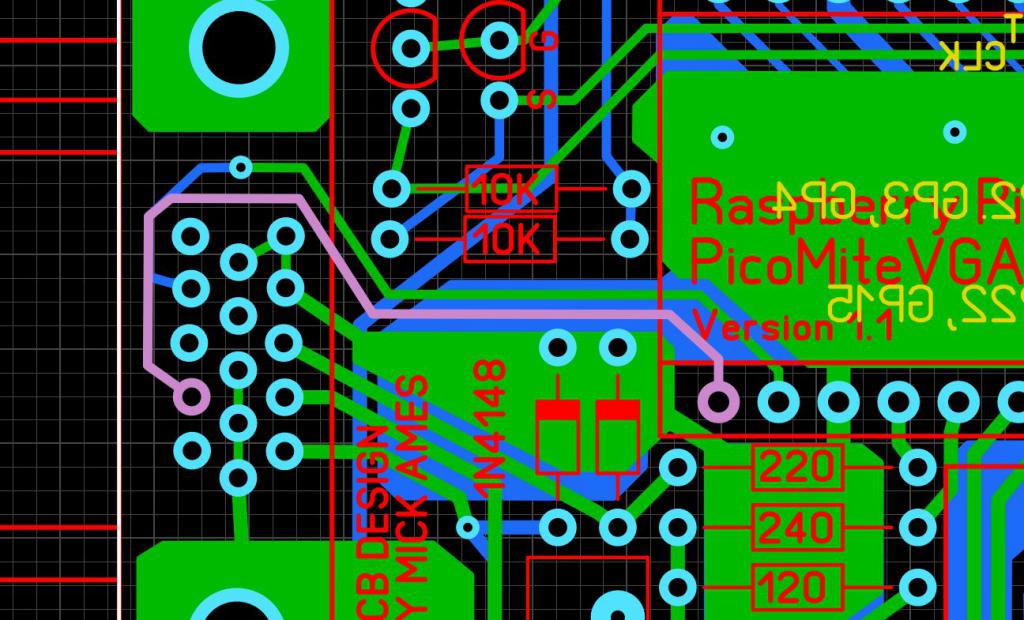 Smoke makes things work. When the smoke gets out, it stops! |
||||
| matherp Guru Joined: 11/12/2012 Location: United KingdomPosts: 11499 |
I know Grogster does it and is successful but I think laying out even a simple PCB without starting with a schematic is asking for problems. The "bug" in your layout could simply not happen if you had a schematic and use any decent package to confirm correspondence between schematic and layout and therefore to check layout errors My advice to anyone designing PCBs. Start with the schematic and use it to derive the layout. I have NEVER had a design with a layout issue. The only changes are always because the schematic has a design error or to enhance a design. The image below shows the checks DesignSpark does and only when there are no errors, or they are ones I accept (e.g. silkscreening outside board area) do the gerbers get created 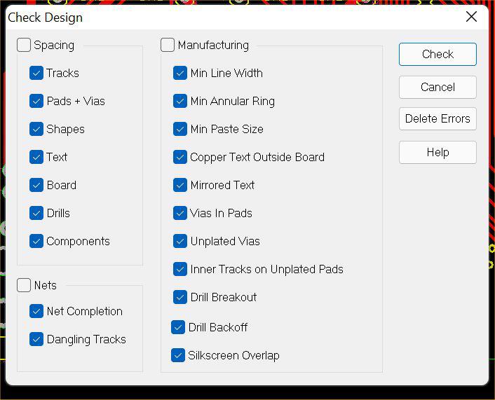 |
||||
| Mixtel90 Guru Joined: 05/10/2019 Location: United KingdomPosts: 8904 |
DRAT!!!! Will fix it.... PicoMiteVGAmini 12.zip PicoMiteVGAmini 12 extras.zip At one time I used to do that, Peter, when I was playing with both Eagle and KiCAD. Unfortunately Eagle is now priced out for anything of any real use and this little fanless PC has very little storage. I could probably use KiCAD, but I'd have to dump most of the libraries - and it's a pig to create new components. At tthe moment I'm using Sprint Layout with TinyCAD. I think there's a way to get TinyCAD to produce a netlist, but I'm not sure it's of any use to Sprint Layout. They aren't intended to work together. The VGA pin error was correct originally, but I messed up when I changed the footprint from one that I'd measured to a more accurate one. I failed to notice that I'd not got everything back. :( Of course, I did the original design without any schematic al all... :) Edited 2021-12-26 18:37 by Mixtel90 Mick Zilog Inside! nascom.info for Nascom & Gemini Preliminary MMBasic docs & my PCB designs |
||||
| Grogster Admin Group Joined: 31/12/2012 Location: New ZealandPosts: 9975 |
I would agree with that. Even in SL6, when I do boards for SOMEONE ELSE, I always request and require a schematic. My own designs, I do out of my head with no schematic, as I can "See" the schematic in my head for my own designs(I draw the schematic later once the PCB has been proven to work), but I always still use the test tool in SL6 to make sure that all tracks are where they should be. Yep, just like me! I do need to point out though, that that is NOT the normal way to do PCB's - you normally always start with the schematic, and work from that. But like I said, I have just got used to doing things my way, and whatever works.... EDIT: I am thinking about doing a custom version of the Colour PicoMite, and to do that, I WILL BE USING PETER'S SCHEMATIC. So, basically, any design that YOU create, you can layout from your memory(generally speaking), but anyone else's design, you really do need that schematic. Edited 2021-12-26 18:56 by Grogster Smoke makes things work. When the smoke gets out, it stops! |
||||
| The Back Shed's forum code is written, and hosted, in Australia. | © JAQ Software 2026 |
