
|
|
Forum Index : Microcontroller and PC projects : Thinking about a new Pico PCB design for integrating into a keyboard
| Author | Message | ||||
| Amnesie Guru Joined: 30/06/2020 Location: GermanyPosts: 757 |
Hi Mick! Length is only a problem because it must (or should) fit into an existing keyboard. But I managed everything to fit within my determined specs. At least I would say you can't go smaller with through hole components... So here is the PCB so far: 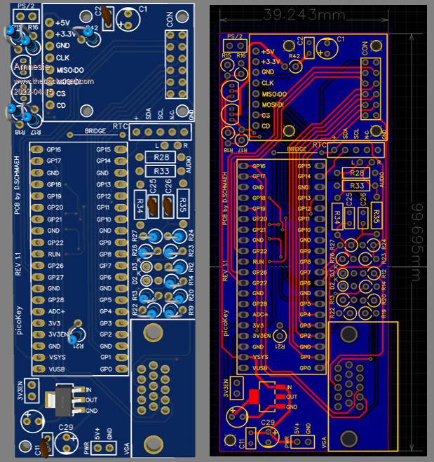 The reset switch must be wired externally, as well as the power jack. But I think this is a good thing, you can place it whre you like. Most importantly the VGA connector fits. Edited 2022-04-15 16:18 by Amnesie |
||||
| Volhout Guru Joined: 05/03/2018 Location: NetherlandsPosts: 5931 |
Looks like a good project, but you may want to revisit the choice for resistors. I did this (hack a keyboard to convert it to a MMbasic computer) using a CMM1. I noticed the height inside the keyboard is not that much. When you have a vertical resistor UNDER the picomite the total height may exceed space you have. Maybe place it flat. At the VGA connector side the height must be okay otherwise it won't fit at all. But similar for R15-18, R42 (under the SD card slot) and C1 (under the SD card slot). For the resisors (there is no place to lay them flat) you could use SMT resistors (1206) that are not to hard to solder. The capacitors... either - move them to an area where they are not UNDER another board - rotate the footprint so you can bend them over to lay flat. Good luck... Volhout (*) On the CMM1 there where 7mm height headers to support an Arduino shield. I had to remove these since there was only 7mm height in the keyboard (and the PCB was 1.6mm thick with 1mm soldering at the bottom side). Edited 2022-04-15 16:24 by Volhout PicomiteVGA PETSCII ROBOTS |
||||
| Mixtel90 Guru Joined: 05/10/2019 Location: United KingdomPosts: 8911 |
It's a pity it's PS/2. There are a lot of little bluetooth and USB keyboards that are very slim. You could mount one of those as the top of a box with the PicoMite in it. A bit like I did with this foamboard & hot glue RPi 3B keyboard: 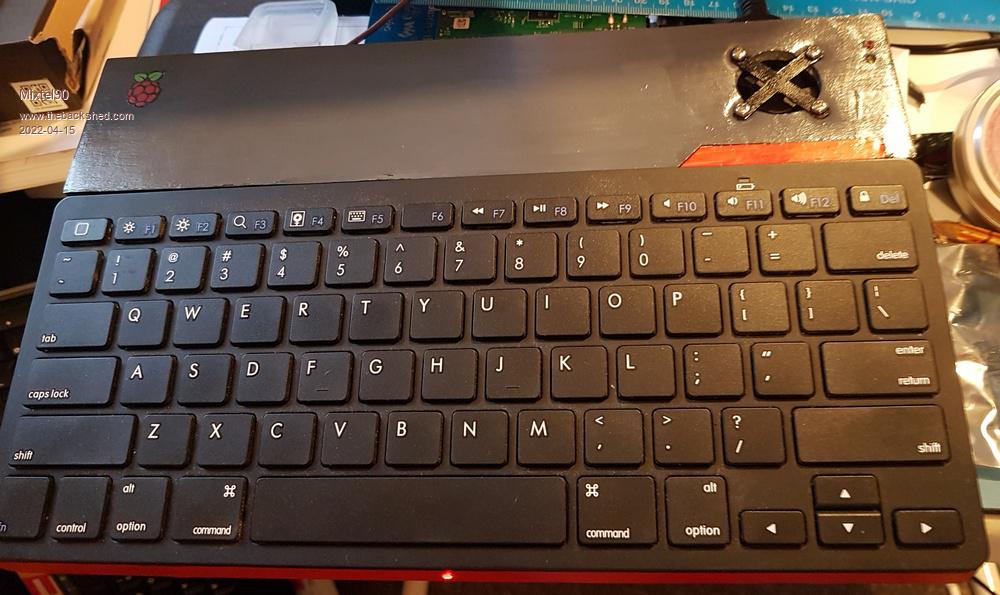 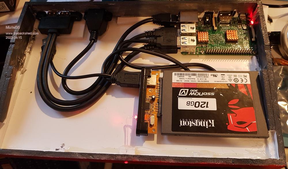 Mick Zilog Inside! nascom.info for Nascom & Gemini Preliminary MMBasic docs & my PCB designs |
||||
| Volhout Guru Joined: 05/03/2018 Location: NetherlandsPosts: 5931 |
Look here CMM1 in keyboard PicomiteVGA PETSCII ROBOTS |
||||
| Amnesie Guru Joined: 30/06/2020 Location: GermanyPosts: 757 |
@ Mick Speaking for myself I am glad it is PS/2 because most USB keyboards are cheap rubber dome and not mechianical this is a really really important thing for me. And there are indeed slim mechanical keyboards! Look at the Cherry G84-4100. This keyboard is interesting because it has a rectangular (overall keys) shape and you can build it into another case. But Peter just triggered me to try wether it is possible to fit a picoVGA into a keyboard... Even if this will not succeed, we (or at least I) have a small footprint picoVGA :) Here is the new update, suggested by Volhout 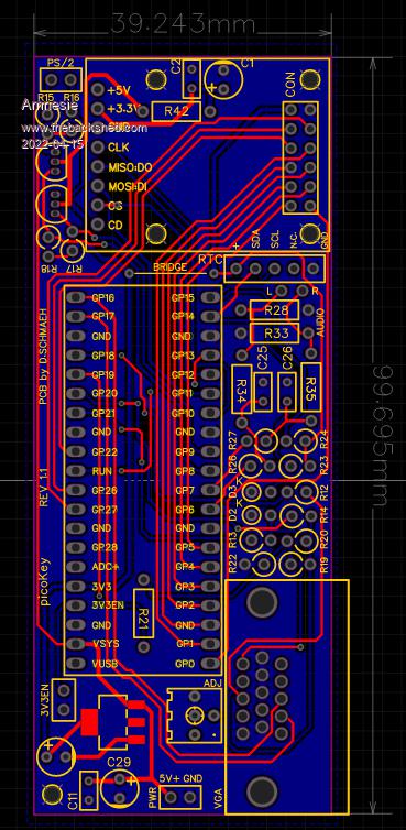 Edited 2022-04-15 16:52 by Amnesie |
||||
| Mixtel90 Guru Joined: 05/10/2019 Location: United KingdomPosts: 8911 |
I can beat you on keyboards... �:) The old Nascom computers came with Licon keybords. These have no contacts whatsoever. About the only way you can damage them is with a hammer. There's a bit about them on my web site. Clacky enough to deafen most people. :) Edited 2022-04-15 17:07 by Mixtel90 Mick Zilog Inside! nascom.info for Nascom & Gemini Preliminary MMBasic docs & my PCB designs |
||||
| Amnesie Guru Joined: 30/06/2020 Location: GermanyPosts: 757 |
Wow, okay this is a really impressive piece of technology! With magnets... I have never seen something like this before. I'll take my young age as an excuse :) Edited 2022-04-15 17:14 by Amnesie |
||||
| Tinine Guru Joined: 30/03/2016 Location: United KingdomPosts: 1646 |
I always seem to bugger up the fold-out legs on my keyboards or end-up spilling coffee on the keys. How about a wedge that sits under the keyboard? Craig |
||||
| Amnesie Guru Joined: 30/06/2020 Location: GermanyPosts: 757 |
Okay, �there will be two versions. One, on the left will ment to be for some "internal use" where a keyboard is directly connected. However, the second is a simple mini version of the picoVGA, where underneath the SD-breakout is the PS/2 (Mini-Din) connector available. The GPIO is on the far left and can be connected via a ribbon cable or handwired to some outlets, or even attached to a male / female counterpart PCB (sandwitch style). Every version, of course, has it's downside due to the limited space. As soon as I have tripple checked with the schematics I release the Gerber files and kiCad etc. to the public to do whatever you want with it. Modify it futher to fit your needs. 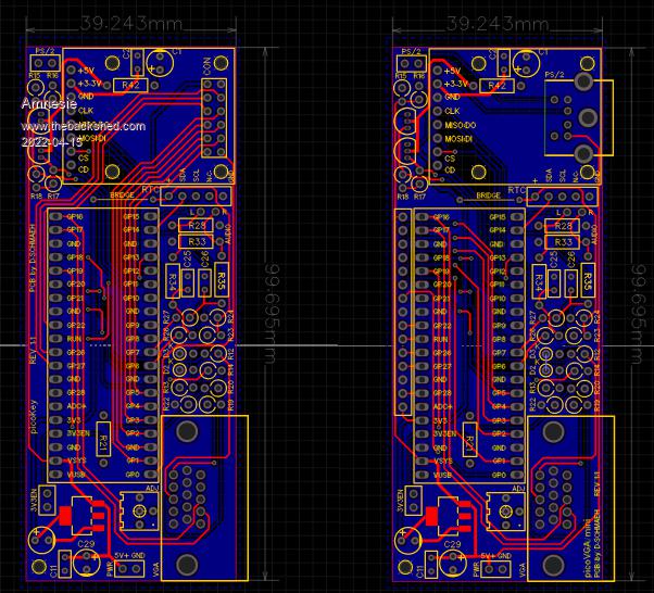 Edited 2022-04-15 20:44 by Amnesie |
||||
bigmik Guru Joined: 20/06/2011 Location: AustraliaPosts: 2981 |
GDay All, I did a little bit of a sketch to toss the idea around. I looked at my keyboard (albiet a USB one) and thought along these lines 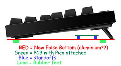 I think you could use a bit of 3mm acrylic (or Aluminium) sheet cut and attached to the under side of the keyboard with the feet extended and this should give a small area to mount your boards and only raise the keyboard height by 5-6mm Kind Regards, Mick Mick's uMite Stuff can be found >>> HERE (Kindly hosted by Dontronics) <<< |
||||
| robert.rozee Guru Joined: 31/12/2012 Location: New ZealandPosts: 2528 |
just a suggestion: make the PCB assembly absolutely flat. no plugs or sockets, just 90-degree pin headers for keyboard and VGA. NO THROUGH-HOLE COMPONENTS UNLESS THEY HANG HORIZONTALLY OFF THE SIDE OF THE PCB. use (large size) SMD resistors, etc. if you must have an RTC module, strip off the battery holder and place it beside the module, sunken into the PCB. then just affix the PCB to the underside of your keyboard with double-sided foam tape. cover the component side of the PCB with a sheet of clear acetate plastic. chop the keyboard's cable short and wire it to a matching 6-pin dupont plug. similarly, make a custom VGA cable. this way, when you spill coffee on the keyboard, you can simply peel off the PCB and attach it to a new keyboard. cheers, rob :-) |
||||
| Tinine Guru Joined: 30/03/2016 Location: United KingdomPosts: 1646 |
Whoa, nice keyboard rendering, Mick �  Just thinking that this could even be a small tapered enclosure, dimensioned to suit the electronics and still 3d printable(?) I realise that double-sided tape sounds a bit cheesy but it has bailed me out enough that I have grown to respect it �  So, a 3d-printed, tapered enclosure bonded to the underside of the KB? Craig Edit: Oh, didn't see Rob's post Edited 2022-04-16 14:55 by Tinine |
||||
| Tinine Guru Joined: 30/03/2016 Location: United KingdomPosts: 1646 |
Custom VGA cable � Available as male or female Craig Edited 2022-04-16 15:15 by Tinine |
||||
TassyJim Guru Joined: 07/08/2011 Location: AustraliaPosts: 6538 |
That links to a 2 row 15 pin connector, not 3 row. Jim VK7JH MMedit |
||||
| Tinine Guru Joined: 30/03/2016 Location: United KingdomPosts: 1646 |
Just testing Better price for the right type on AE Craig |
||||
| Tinine Guru Joined: 30/03/2016 Location: United KingdomPosts: 1646 |
Just testing Better price for the right type on AE Craig |
||||
| Amnesie Guru Joined: 30/06/2020 Location: GermanyPosts: 757 |
As I said before SMD components will not be part of this design (except the AMS1117 LDO). Of course you are right, that with SMD components a lot space and height can be saved.. But not everyone is able to solder this. Maybe I am doing a SMD design later on (most certainly I think). Greetings Daniel |
||||
| Amnesie Guru Joined: 30/06/2020 Location: GermanyPosts: 757 |
Yep, I had in mind those, too. This would make a lot of free room on the pcb! Edited 2022-04-16 18:51 by Amnesie |
||||
| Mixtel90 Guru Joined: 05/10/2019 Location: United KingdomPosts: 8911 |
If you keep to the large sizes of SMD they aren't all that difficult to solder with a little practice. It might be an idea, though, to seriously consider using SMD to mount the PicoMite and perhaps mounting a miniUSB connector to connect to it. That's much less fragile than the microUSB and is much easier to solder. A socketed PicoMite sticks up about 15mm from the surface of the pcb. That's more than either a VGA or PS/2 connector. Mick Zilog Inside! nascom.info for Nascom & Gemini Preliminary MMBasic docs & my PCB designs |
||||
| al18 Senior Member Joined: 06/07/2019 Location: United StatesPosts: 238 |
FYI the Pico is designed with castellated pads, so it can be soldered flat to a circuit board |
||||
| The Back Shed's forum code is written, and hosted, in Australia. | © JAQ Software 2026 |
