
|
|
Forum Index : Microcontroller and PC projects : Will the Pico directly drive this MOSFET?
| Author | Message | ||||
| Mixtel90 Guru Joined: 05/10/2019 Location: United KingdomPosts: 8682 |
I can't see why that wouldn't work... Can you try a higher gate voltage? I think it's safe up to 20V so you have plenty of possibility. You should be able to get about 11A through it with about 3V3 on the gate. Edited 2022-06-09 02:26 by Mixtel90 Mick Zilog Inside! nascom.info for Nascom & Gemini Preliminary MMBasic docs & my PCB designs |
||||
| Tinine Guru Joined: 30/03/2016 Location: United KingdomPosts: 1646 |
Oh Crapola!!! Mick, I'll be right over so you can kick my butt  Brand-new device, super stiff to push into brand new breadboard....but it's making bad contact These last tests, I already performed before posting but this time I disturbed the FET. Gonna solder this stuff in to a proto board. You guys ROCK! Many thanks for the assistance  Craig. |
||||
| Mixtel90 Guru Joined: 05/10/2019 Location: United KingdomPosts: 8682 |
That was unfortunate! Glad it's working now though. :) Mick Zilog Inside! nascom.info for Nascom & Gemini Preliminary MMBasic docs & my PCB designs |
||||
| CaptainBoing Guru Joined: 07/09/2016 Location: United KingdomPosts: 2171 |
cool, check back when the breadboard is eliminated. I am betting you go straight through with greens all the way. as a point of note, lots of people put a pull-down resistor to the gate. it's a brief safety thing to stop false triggering on the gate (which you have already experienced) in the milli-seconds before your CPU has control of it. I don't bother because the setup on the drive pin (to output and Lo) is just about the first thing I do on boot. it's my risk but the resistor will slow the Hi-going edges a bit which is generally undesirable with power drive (more-so with PWM). please yourself here. Some also put a resistor in series with the gate because the effective capacitance can give spikes of current when the state changes and you *might* over-tax the IO pin - sinking or sourcing while you charge the capacitance. It's only incredibly brief - uS and check your device to see if the rise/fall time on the IO versus the capacitance of the gate will be a problem. I have never had any trouble but the capacitance of some devices can be considerable (the gate on FQP30 can look like 1nF at 1MHz, so keep your PWM nice and slow and it won't be a problem) and you might see considerable joules with the current flowing in and out on very rapid state changes. Again, please yourself - I don't bother. Never had a problem in either case with the IO pins and the power MOSFETs run nice and cool so the risk involved to save $0.03 is worth it �As your circuit is virtually identical to my own I can't see you'd get problems. What is the resistance (and design) of your heater element(s)? Mine are two 12R aluminium clad 50mm beasties in parallel so 6R total bolted to the underside of the aluminium bed plate.just checked - my PWM is 20Hz not 25... small point Edited 2022-06-09 03:07 by CaptainBoing |
||||
| Mixtel90 Guru Joined: 05/10/2019 Location: United KingdomPosts: 8682 |
The gate resistor is also good, if right next to the gate, for controlling parasitic oscillation. 100R - 470R is generally fine. I don't bother with small devices, but it's nice to do with power devices where the oscillation translates as extra dissipation. Mick Zilog Inside! nascom.info for Nascom & Gemini Preliminary MMBasic docs & my PCB designs |
||||
| Tinine Guru Joined: 30/03/2016 Location: United KingdomPosts: 1646 |
Frustrating Even quick mock ups, I use good quality connectors and ferrules on every wire....didn't suspect the breadboard for a minute. 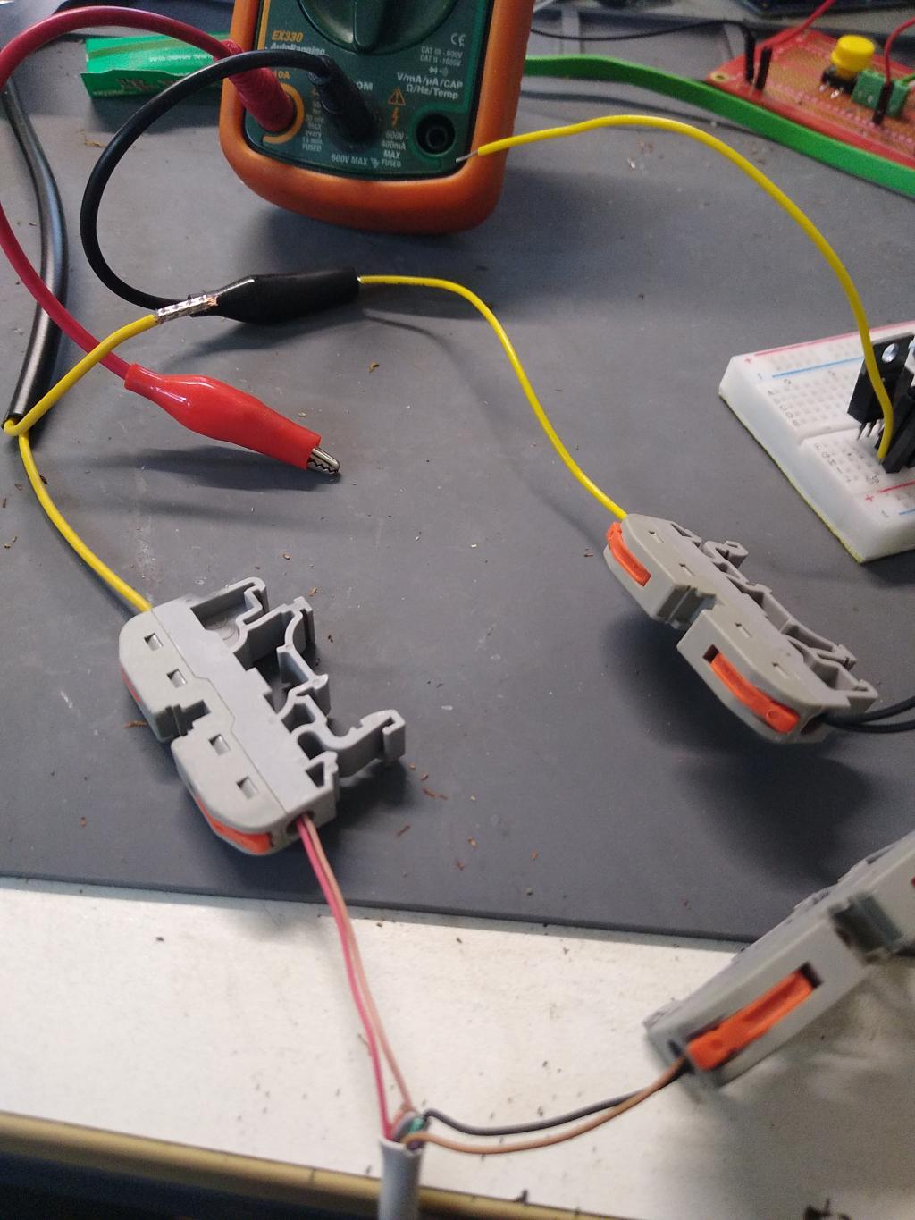 Craig |
||||
| pwillard Guru Joined: 07/06/2022 Location: United StatesPosts: 339 |
Cheap breadboards can "getcha". https://eater.net/breadboards |
||||
| Tinine Guru Joined: 30/03/2016 Location: United KingdomPosts: 1646 |
Info would have been useful to me....8 hours ago Craig |
||||
| Tinine Guru Joined: 30/03/2016 Location: United KingdomPosts: 1646 |
 Hmmm, Ben Eater is recommending the wrong wire-stripper (Knipex Automatic) for this gauge of wire. I have the exact same device and love it but only for heavier gauges. The above is far superior but you certainly don't need to pay Knipex prices Edited 2022-06-09 05:45 by Tinine |
||||
| Tinine Guru Joined: 30/03/2016 Location: United KingdomPosts: 1646 |
Hmmm, no longer convinced that my breadboard was the issue...it takes time to start conducting. Either with PWM or straight to 3.3V. However, I am also having other issues...the USB comm's are failing again and this is a completely different Pico and 24V PSU. As soon as I start testing and I try to send a new PWM command from the terminal....dead comm's  Gonna set my desk up with all kinds of options to try. I'm growing to suspect the Pico's SMPS and so I'll rig-up an E-100, an MX170 and compare with the Pico. Think I'll switch over to my Panasonic Toughbook to eliminate my powered USB hub. Gonna get to the bottom of this  BRB Craig |
||||
| matherp Guru Joined: 11/12/2012 Location: United KingdomPosts: 11097 |
Have you got a resistor between the Pico and the Mosfet gate? The Mosfet gate acts like a capacitor and will have a big in-rush current at each transition. This needs controlling with a series resistor to avoid overloading (temporarily) the Pico output |
||||
| pwillard Guru Joined: 07/06/2022 Location: United StatesPosts: 339 |
That... and a higher value resistor from the gate pin to GND ( IE; 100K or so) to make sure it doesn't float or hold a charge when you don't want it to. |
||||
| Tinine Guru Joined: 30/03/2016 Location: United KingdomPosts: 1646 |
@matherp and pwillard Not yet but that's the plan...Thanks guys |
||||
| Tinine Guru Joined: 30/03/2016 Location: United KingdomPosts: 1646 |
OK, still on the Pico and the addition of the resistors, 10K from PWM to gate and 100K to ground....The USB issue has disappeared ( ).Device is conducting (sinking 4A), no matter what. PWM is working out of the Pico but at the Gate, after the 10K resistor, all I have is 0.054V  Craig |
||||
| matherp Guru Joined: 11/12/2012 Location: United KingdomPosts: 11097 |
Sounds like the MOSFET is backwards |
||||
| Tinine Guru Joined: 30/03/2016 Location: United KingdomPosts: 1646 |
Was gobsmacked when I smoked a Pico the other day because I can be pretty anal when it comes to checking connections prior to power up. Just dashed to CPC.Farnell and grabbed the other devices listed in this thread. I have my E-100, MX170 and Pico lined up. Would love to replicate what the Cap'n has going but I wanna see what needs to happen for the Pico. Gonna be a FETish Friday |
||||
| pwillard Guru Joined: 07/06/2022 Location: United StatesPosts: 339 |
Honestly... 10K from the GPIO pin to the gate seems a bit high. �Try lowering to something between 220 Ohms and 1K. �With 220 and 100K to GND... you still get 3.2V at the gate... and VOLTAGE is what you need there. Edited 2022-06-10 04:21 by pwillard |
||||
| Tinine Guru Joined: 30/03/2016 Location: United KingdomPosts: 1646 |
Absolutely no clue where the 10K came from. In my head at the time I was sure that it came from Pete....senior moment Craig |
||||
| CaptainBoing Guru Joined: 07/09/2016 Location: United KingdomPosts: 2171 |
I have no schematic coz I just whipped it up on my bench. I will open it up and take photos (the horror! the horror!) |
||||
| CaptainBoing Guru Joined: 07/09/2016 Location: United KingdomPosts: 2171 |
OK, I lied. I did do a schematic... no surprises: 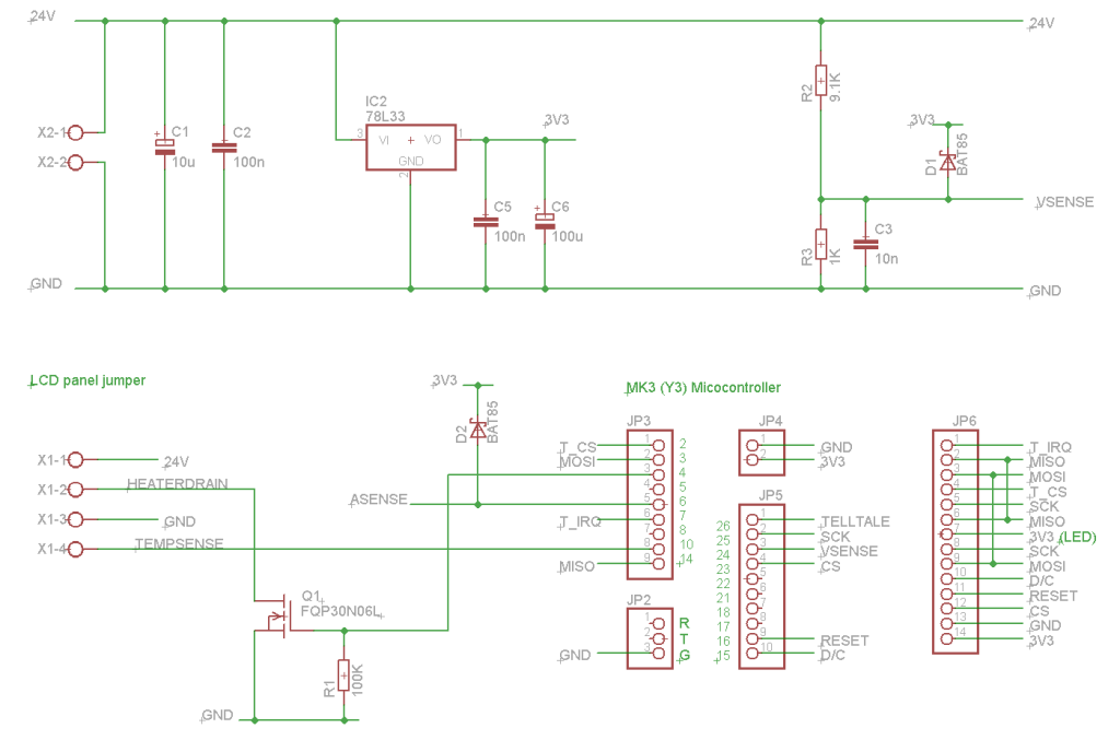 and I just opened it up and took this photo - R1 is omitted as I suspected. 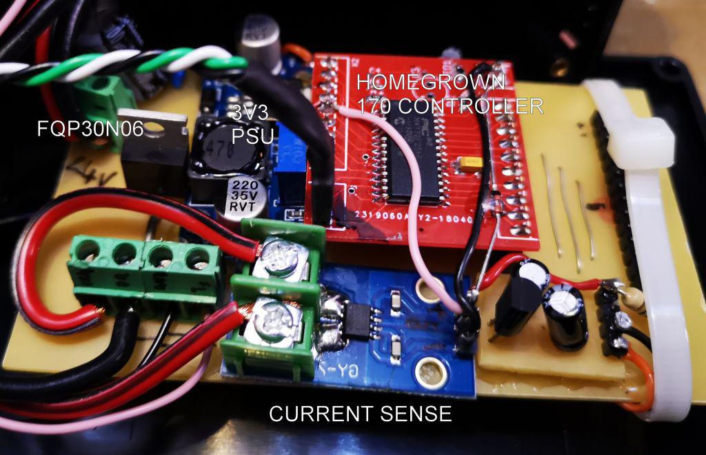 and I did this little vid of the thing in action (may still be processing on YT) https://youtu.be/l5ljYgYmCIk hope this helps Edited 2022-06-10 06:53 by CaptainBoing |
||||
| The Back Shed's forum code is written, and hosted, in Australia. | © JAQ Software 2026 |
