
|
|
Forum Index : Microcontroller and PC projects : ILI9341 Manual?
| Author | Message | ||||
| phil99 Guru Joined: 11/02/2018 Location: AustraliaPosts: 3296 |
There are two ways to do it:- As above, but using free pins. Or the SD card can share the System SPI bus and only the Chip Select pin needs to be specified in OPTION SDCARD SD Card Support - See pages 37 & 78 in the PicoMite manual (not PicoMiteVGA manual). PS If you need to change a existing SD setup first remove it with OPTION SDCARD DISABLE |
||||
| VK2AHB Regular Member Joined: 28/07/2022 Location: AustraliaPosts: 51 |
Another problem I have is the LCDs I'm using aren't labelled the same as on P47. One is a MCUFriend (blue) , the other is tftlcd for arduino (spiflash) (orange). Anyone using these? Paul |
||||
| matherp Guru Joined: 11/12/2012 Location: United KingdomPosts: 11551 |
Pics? Then we can see if they are supported |
||||
| stanleyella Guru Joined: 25/06/2022 Location: United KingdomPosts: 2807 |
arduino boards tend to be 5v logic. arduino lcd boards would be. |
||||
| VK2AHB Regular Member Joined: 28/07/2022 Location: AustraliaPosts: 51 |
I upladed a photo, where did it go? Paul |
||||
| VK2AHB Regular Member Joined: 28/07/2022 Location: AustraliaPosts: 51 |
I'll try again... 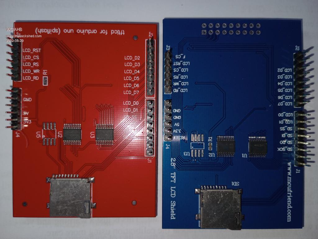 |
||||
| matherp Guru Joined: 11/12/2012 Location: United KingdomPosts: 11551 |
Both these displays are wired parallel (not SPI) and are not supported on the PicoMite |
||||
| VK2AHB Regular Member Joined: 28/07/2022 Location: AustraliaPosts: 51 |
OK, thanks for that. I'll have to give up until I get one (or two) that suit. For the arduino I used a 1.8" TFT with this code #include <Adafruit_ST7735.h> #include <Adafruit_GFX.h> #define TFT_CS 10 #define TFT_RST 9 #define TFT_DC 8 Adafruit_ST7735 tft = Adafruit_ST7735(TFT_CS, TFT_DC, TFT_RST); although I think I only used SDA and CLK ... quite some time ago. Googling ST7735 I found this, using Circuit Python. https://www.youtube.com/watch?v=KaGHxvVnKQ4 The 1.8" TFT 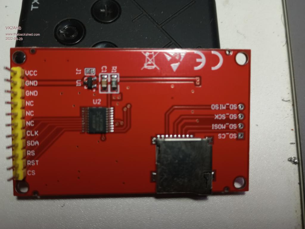 Paul |
||||
| JohnS Guru Joined: 18/11/2011 Location: United KingdomPosts: 4336 |
The ST7735 is in the Pico manual. John |
||||
| stanleyella Guru Joined: 25/06/2022 Location: United KingdomPosts: 2807 |
OPTION LCDPANEL ST7735, OR, DC, RESET, CS Initialises a TFT display using the ST7735 controller. This supports 160 * 128 resolution. nice mmbasic supports many displays |
||||
| VK2AHB Regular Member Joined: 28/07/2022 Location: AustraliaPosts: 51 |
Small Steps. I tried connecting the ST7735 with CS, RST and RS but didn't work. I then hoped that I could configure the display as ST7735I2C but no luck. I then dragged out the OLED display and confirmed that it was SSD1306I2C. It performed the Adafruit graphics test with the Arduino. So I plugged it in, configured it and got this! 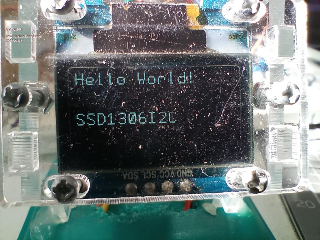 Paul |
||||
| phil99 Guru Joined: 11/02/2018 Location: AustraliaPosts: 3296 |
Had you set OPTION SYSTEM I2C sdapin, sclpin before OPTION LCDPANEL ST7735, OR, DC, RESET, CS ? "Specify the I2C port for system devices. The PicoMite uses a specific I2C port and pins for use by system devices (LCD panel, and RTC). leaving the other for the programmer. This command specifies which pins are to be used, and hence which of the I2C ports is to be used. The pins allocated to the SYSTEM I2C will not be available for other MMBasic SETPIN settings but can be used for additional I2C devices using the standard I2C command. Note: I2C(2) OPEN and I2C(2) CLOSE are not available in this case. This command must be run at the command prompt (not in a program)." |
||||
| VK2AHB Regular Member Joined: 28/07/2022 Location: AustraliaPosts: 51 |
B-b-but when I did that, it said SPI not configured. Looking at the SPI manual I configured SPI2 with GP28, 27, 26. But then, what parameters to SPI OPEN? And how do those pins relate to DC, RST and CS? I really need some assistance in getting this going. Sorry! Paul |
||||
| matherp Guru Joined: 11/12/2012 Location: United KingdomPosts: 11551 |
Follow the manual as though the display was a ILI9341 but substitute ST7735 in the OPTION LCDPANEL command - see the section "Example LCD Panel Configuration" |
||||
TassyJim Guru Joined: 07/08/2011 Location: AustraliaPosts: 6539 |
What does OPTION LIST give you? I suspect that you don't have OPTION SYSTEM SPI set. You need to set: OPTION SYSTEM SPI CLKpin, MOSIpin, MISOpin OPTION SDCARD CS OPTION LCDPANEL ST7735, OR, DC, RESET, CS OPTION TOUCH IRQpin, CSpin The system does the opening etc. SD and touch may not apply to you. Jim VK7JH MMedit |
||||
| stanleyella Guru Joined: 25/06/2022 Location: United KingdomPosts: 2807 |
sir, his photo is i2c ssd1306 Ili9341 is spi. If it is an ili9341 and set up from info in the manual it works. I think it is different that options are set up in a terminal as command lines and not in a program. I know there is a list of which are command line and which can be used in a program. it is a good display using mmbasic, hope you get it to work. stan |
||||
| Mixtel90 Guru Joined: 05/10/2019 Location: United KingdomPosts: 8913 |
Think of the OPTIONS as DIP switches that define how the hardware works. Most do things that you wouldn't or couldn't do inside a program. The fact that you set them from a console is no problem. It's a bit like being root in linux - and you don't (shouldn't) ever run as root. Mick Zilog Inside! nascom.info for Nascom & Gemini Preliminary MMBasic docs & my PCB designs |
||||
| TassyJim Guru Joined: 07/08/2011 Location: AustraliaPosts: 6539 |
If I am looking at the correct image, your ST7735 is a 3 wire SPI display. Connect SDA to MOSI and leave MISO unconnected. You will be limited in some graphics capability because you can't read data from the ST7735 module. Jim VK7JH MMedit |
||||
| VK2AHB Regular Member Joined: 28/07/2022 Location: AustraliaPosts: 51 |
Hi Jim, Thanks for that, but I am still in the dark :-) With a new install of the firmware, I do 1. OPTION SDCARD GP13, GP10, GP12, GP12 ** This is instruction on the VGA board 2. Now what? OPTION SYSTEM SPI xx,yy,zz? Can you give me actual numbers please? 3. OPTION LCDCARD RL, aa,bb,cc Which is MOSI? The display has CS, RST, RS SDA, CLK. I tried OPTION SYSTEM SPI GP2, GP3, GP0. is that right? Flying blind here. Then tried OPTION LCDCARD various TX and RX pins, told pins are reserved on startup. Maybe the VGA version doing that?? Paul |
||||
| TassyJim Guru Joined: 07/08/2011 Location: AustraliaPosts: 6539 |
The VGA version of the picomite doesn't do LCD displays so forget anything you read there. Start by clearing out any options you have set with OPTION RESET Then OPTION SYSTEM SPI CLKpin, MOSIpin, MISOpin where you tell the pico which pins you have chosen for CLK MOSI and MISO Which pins you are using is up to you. There are a few choices. The SD card, if used will share the SYSTEM SPI pins, you just have to tell the pico which additional pin you used for the CS. OPTION SDCARD CS Next it's the display: OPTION LCDPANEL ILI9341, orientation, DCpin, RESETpin, CSpin You choose which pins you use for DC, RESET and CS Your panel doesn't have MISO available but it has to be specified under SYSTEM SPI. Connect SDA to MOSI and leave MISO unconnected. There is also an optional backlight control pin which gets added to the OPTIONs Its further down the manual under 'Backlight' If your display does have the backlight pin, it may be 'inverted' Once the display is configured try BACKLIGHT 50 to set it half way then try BACKLIGHT 90 or 10 to see which way increases brightness. I don't think your module has a backlight control. If your panel has touch, you will have to configure it as well: OPTION TOUCH IRQpin, CSpin Jim VK7JH MMedit |
||||
| The Back Shed's forum code is written, and hosted, in Australia. | © JAQ Software 2026 |
