
|
|
Forum Index : Microcontroller and PC projects : I did it again
| Author | Message | ||||
lew247 Guru Joined: 23/12/2015 Location: United KingdomPosts: 1709 |
Thanks Tom The manual says SETPIN rx, tx, COM1 which should in this case be GP1, GP0? I tried both SetPin GP0, GP1, COM1 and SetPin GP1, GP0, COM1 and went through all the baud rates but nothing on the console/ I'll leave it running for a few hours in case it only shows data once it has a valid lock |
||||
| Volhout Guru Joined: 05/03/2018 Location: NetherlandsPosts: 5953 |
Hi Lewis, This should be your option configuration for touch and display 'OPTION LCDPANEL ILI9341, OR, DC, RESET, CS OPTION LCDPANEL ILI9341, "L",GP15,GP14,GP13 'OPTION SYSTEM SPI CLK,MOSI,MISO OPTION SYSTEM SPI GP18, GP19, GP16 'OPTION TOUCH T_CS,T_IRQ OPTION TOUCH GP12, GP8 PicomiteVGA PETSCII ROBOTS |
||||
| stanleyella Guru Joined: 25/06/2022 Location: United KingdomPosts: 2807 |
from the picomite manual page 47 for ili9341 OPTION SYSTEM SPI GP18, GP19, GP16 OPTION SDCARD GP22 OPTION LCDPANEL ILI9341, L, GP15, GP14, GP13 OPTION TOUCH GP12, GP11 I followed the manual and touch gp12,gp11 not gp12,gp8 The manual circuit and set up works. The sd card seems to use spi but the cs line gp22. is it software or hardware? can I use gp2 ,gp3,gp4,gp5 for I2C when using ili9341 using the manual circuit and setup please? |
||||
| Mixtel90 Guru Joined: 05/10/2019 Location: United KingdomPosts: 8913 |
On the PicoMite SPI chanels CS is always handled by MMBasic, not in hardware. You can specify any pin for CS. The I2C channels, even though they can be allocated to the same pins as SPI channels, are separate devices so yes, you can use I2C on any other suitable pins as well as having SPI devices connected. When using a ILI9341 it's normal to connect the display, touch controller and SD card to the same SPI. They have individual CS lines so there is no conflict. Mick Zilog Inside! nascom.info for Nascom & Gemini Preliminary MMBasic docs & my PCB designs |
||||
| stanleyella Guru Joined: 25/06/2022 Location: United KingdomPosts: 2807 |
Thank you Mick. Nice to know I can use I2C and ili9341 with touch and sd card. I have a couple of PCA9685 chips. They work ok with 8bit chips. I got 2 of them running 18 rc servos... but not in mmbasic yet.. one project at a time and it is all learning.. but fun. https://www.youtube.com/watch?v=YtKqmKKk4gk Does the circuit in the manual use one channel? It uses spi0 and spi1. Is that hardware spi? Is there a better way of wiring the ili9341 than the circuit in the manual?... if it is all software but what is software spi? I read an sd card reader is "bit banged". Is the ili9341 sd card reader bit banged as it is connected to spi except cs to gp22. The display seems to run very fast for software spi. Edited 2022-08-26 07:52 by stanleyella |
||||
| thwill Guru Joined: 16/09/2019 Location: United KingdomPosts: 4369 |
Hi Lewis, I have done a minimal wire up of my identical M9N-5883 GPS to the PicoMite and it seems fine - note that you don't need a lock for this to write output to the console. SetPin GP0, GP1, COM1 Open "COM1:115200" As Gps, 0, 1 Do �Pause 100 Loop The correct wiring is GPS � � | Pico --------+--------- 5V � � �| 40 / VBus TX � � �| �1 / GP0 RX � � �| �2 / GP1 Gnd � � | 38 / Gnd The best guess of this ignoramus is that (excluding any release of the magic smoke) you have TX-TX and RX-RX connected directly instead of crossed TX-RX, RX-TX. This argument is strengthened by the fact that in the diagrams of the Pico posted earlier you have GP0 labeled RX and GP1 labeled TX ... they are in reality the other way round ... though you may have labeled them according to what they are connecting to rather than what they are ??? Best wishes, Tom Edited 2022-08-26 17:21 by thwill MMBasic for Linux, Game*Mite, CMM2 Welcome Tape, Creaky old text adventures |
||||
| lew247 Guru Joined: 23/12/2015 Location: United KingdomPosts: 1709 |
Thanks Tom I had an issue with the GPS receiver, the soldering I had done to connect it was that bad it was joining 2 tracks Once I sorted that out this morning it "seems" to be receiving properly now, I'm using the Ublox program to make certain the GPS is functioning properly before moving back to the Pico again |
||||
| Volhout Guru Joined: 05/03/2018 Location: NetherlandsPosts: 5953 |
This is presented by Disco4Now '------------------------------------------------------------------------------' ' Micromite library for PCA9685 ' ' Uses PCA9685 16-channel PWM over I2C to support 16 Servos or PWM pins ' ' ' ' ' ' Author: Disco4now TBS Forum ' ' ' dim ProgTitle$ = "PCA9685 Test Suite" ' ' ' Dim ProgVer$ = "v1.0.0" ' ' ' Dim ProgDate$ = "03-Apr-2018" ' '------------------------------------------------------------------------------' 'Code for a Micromite to communicate with a PCA9685 16-channel PWM over I2C. 'Also contains routine to allow calibration of servos. 'The console input is scanned and characters read as they are typed ' ServoMIN(16),ServoMAX(16) hold min and max pulse widths for 0 and 180 deg respectively. ' nominal values 800 and 2200 but adjust to suit your particular servos ' calibration values for each servo ' 0-9,a-f used to select the servo to calibrate. ' SPACEBAR sets servo near the centre i.e 90 deg for nominal range of 0-180 ' right arrow sets servo to 180 deg.SPACEBAR to reurn to centre. ' PgUp/PgDn increase/decrease pulse width by 10uS. Up/Down Arrows increase/decrease by 1uS ' Press SPACEBAR and current value will print to console. ' When the servo is operating correctly then record the max/min values and used them ' to set ServoMIN(x) and ServoMAX(x) values in the PWMInit() routine. ' nominal values 800 and 2200 but adjust to suit your servos ' e.g. ' ServoMIN(0)=480:ServoMAX(0)=2140 ' ServoMIN(1)=480:ServoMAX(1)=2085 ' ServoMIN(2)=460:ServoMAX(2)=2125 ' Once these are set you just use ' SERVOSet(id,angle) ' to set individual servo to desired angle Option Explicit Option Default NONE '================================================================================================ ' Data Variables '================================================================================================ Dim integer loc0last,loc0now,loc1last,loc1now,loc2last,loc2now,GetCon=0,GetCom1=0,GetCom2=0 Dim integer i,id=0,highlow=0 '================================================================================================ ' Program Initialization '================================================================================================ Print "Starting " + ProgTitle$ + ": " + ProgVer$ + " - " + ProgDate$ settick 100,IsSerialOrConsoleComplete,1 'Initialise the PCA9685 16-channel PWM over I2C at frequency of 1000 PWMInit 50 '50Hz for 20ms pulse period represented by 4096 ticks 'Uncomment to sweep servos at start up. ' for i=0 to 15 ' SERVOset i,0 ' pause 500 ' SERVOset i,180 ' pause 500 ' SERVOset i,90 ' pause 500 ' next i '================================================================================================ ' Main program loop '================================================================================================ do 'Watchdog 40000 'reset after 40 secs on hang '==============================Check Console and Serial Ports==================================== IF GetCon=1 then ReadConsole 'If data in console1 then GOSUB GetConsole END IF IF GetCom1=1 then ReadSerial1 'If data in COM1 then GOSUB GetSerial1 END IF IF GetCom2=1 then ReadSerial2 'If data in COM2 then GOSUB GetSerial2 END IF Loop '================================================================================================ ' Procedures providing program functionality components '================================================================================================ 'Checks console and serial ports for data and sets flag if data has stopped coming in. 'flag triggers read of the data in the main program loop sub IsSerialOrConsoleComplete 'Check console and set flag if data exists and has stopped coming in loc0now=LOC(#0) IF Loc0now>0 then IF loc0now=loc0last THEN 'data finished GetCon=1 'If data in CON then set GetConsole flag else loc0last=loc0now ENDIF END IF 'Check COM1 and set flag if data exists and has stopped coming in ' loc1now=LOC(#1) ' IF loc1now > 0 THEN ' if loc1now=loc1last then 'data finished ' GetCom1=1 ' ELSE ' loc1last=loc1now ' ENDIF ' ENDIF ' 'Check COM2 and set flag if data exists and has stopped coming in ' loc2now=LOC(#2) ' IF loc2now > 0 THEN ' if loc2now=loc2last then 'nothin new ' GetCom2=1 ' ELSE ' loc2last=loc2now ' ENDIF ' ENDIF end sub 'Reads data from the console SUB ReadConsole local char$ LOCAL INTEGER i,j,k j=LOC(#0) char$= INPUT$(100,#0) if char$<>"" then If len(char$)=1 then ' ? char$; ' ? ASC(left$(char$,1)); IF Char$="0" then id=0 IF Char$="1" then id=1 IF Char$="2" then id=2 IF Char$="3" then id=3 IF Char$="4" then id=4 IF Char$="5" then id=5 IF Char$="6" then id=6 IF Char$="7" then id=7 IF Char$="8" then id=8 IF Char$="9" then id=9 IF Char$="a" then id=10 IF Char$="b" then id=11 IF Char$="c" then id=12 IF Char$="d" then id=13 IF Char$="e" then id=14 IF Char$="f" then id=15 if char$=chr$(145) then 'F1 VT100 ? "F1" end if if char$=chr$(146) then 'Home VT100 ? "F2" end if if char$=chr$(147) then 'Home VT100 ? "F3" end if if char$=chr$(148) then 'Home VT100 ? "F4" end if if char$=chr$(149) then 'F1 VT100 ? "F5" end if if char$=chr$(150) then 'Home VT100 ? "F6" end if if char$=chr$(151) then 'Home VT100 ? "F7" end if if char$=chr$(152) then 'Home VT100 ? "F8" end if if char$=chr$(153) then 'Home VT100 ? "F9" end if if char$=chr$(155) then 'Home VT100 ? "F11" end if if char$=chr$(156) then 'Home VT100 ? "F12" end if if char$=chr$(127) then 'up arrow VT100 ? "Del" END IF if char$=chr$(128) then 'up arrow VT100 '? "Up Arrow" if highlow=0 then ServoMIN(id)=ServoMIN(id)+1 else ServoMAX(id)=ServoMAX(id)+1 end if END IF if char$=chr$(129) then 'down arrow '? "Down Arrow" if highlow=0 then ServoMIN(id)=ServoMIN(id)-1 else ServoMAX(id)=ServoMAX(id)-1 end if END IF if char$=chr$(131) or char$=chr$(4) then 'right arrow VT100 MMEdit '?"Right Arrow" SERVOSet(id ,180) highlow=1 END IF if char$=chr$(130) or char$=chr$(19) then 'left arrow VT100 VT100 MMEdit '? "Left Arrow" SERVOSet(id ,0) highlow=0 end if if char$=chr$(132) then ? "INS" end if if char$=chr$(133) then ? "133" end if if char$=chr$(134) then ? "Home" end if if char$=chr$(135) then ? "End" end if if char$=chr$(136) then 'PgUp VT100 If highlow=0 then ServoMIN(id)=ServoMIN(id)+10 else ServoMAX(id)=ServoMAX(id)+10 end if end if if char$=chr$(137) then 'PgUp VT100 if highlow=0 then ServoMIN(id)=ServoMIN(id)-10 else ServoMAX(id)=ServoMAX(id)-10 end if end if if char$=chr$(138) then ? "138" end if if char$=chr$(139) then ? "ALT" end if if char$=chr$(140) then ? "140" end if IF char$=" " THEN ' ? "SPACE BAR" SERVOSet(id ,90) ? id,ServoMIN(id),ServoMAX(id); If highlow=1 then ? " High(180)" else ? " Low(0)" ENDIF endif else ? char$; ? ASC(left$(char$,1)); endif IF ASC(Left$(char$,1))=27 then ? "ESC" end if end if End if End sub '================================================================================================ ' PCA9685 I2C PWM Routines '================================================================================================ 'Code for a Micromite to communicate with a PCA9685 16-channel PWM over I2C. 'Original Author:- Limor Fried/Ladyada for Adafruit Industries 'Ported to MMBasic by Disco4now!, TBS forums '********************************************************************************** ' This is a library for our Adafruit 16-channel PWM & Servo driver ' Pick one up today in the adafruit shop! ' ------> http://www.adafruit.com/products/815 ' These displays use I2C to communicate, 2 pins are required to ' interface. For Arduino UNOs, thats SCL -> Analog 5, SDA -> Analog 4 ' Adafruit invests time and resources providing this open source code, ' please support Adafruit and open-source hardware by purchasing ' products from Adafruit! ' Written by Limor Fried/Ladyada for Adafruit Industries. ' BSD license, all text above must be included in any redistribution '********************************************************************************** SUB SERVOSet(id as integer,angle as integer) 'set individual servo to desired angle local integer tickoff tickoff=4096*(ServoMin(id)+(ServoMAX(id)-ServoMIN(id))*angle/180)/20000 '? tickoff PWMSet(id ,1,tickoff) end sub SUB PWMSetPin(id as integer,value as integer,inv as integer) 'Helper to set pin PWM output. Sets pin without having to deal with on/off tick placement 'and properly handles a zero value as completely off and 4095 as completely on. 'Optional invert parameter supports inverting the pulse for sinking to ground. 'id is PWM output pin, from 0 to 15 'value is the number of ticks out of 4096 to be active, should be a value from 0 to 4095 inclusive. 'inv if true, inverts the output, defaults to 'false' 'clamp value between 0 and 4095 inclusive. if value > 4095 then value=4095 if value < 0 then value=0 if inv=0 then if value=0 then 'special value for fully off PWMSet(id ,4096,0) else if value=4095 then 'special value for fully on PWMSet(id ,0,4096) else PWMSet(id, 0, 4095-value); endif else if value=4095 then PWMSet(id ,4096,0) else if value=0 then PWMSet(id ,0,4096) else PWMSet(id, 0, value); endif endif end sub SUB PWMSet(id as integer,ontick as integer,offtick as integer) 'main routine -sets the PWM output of one of the PCA9685 pins ' id - One of the PWM output pins, from 0 to 15 ' ontick - At what point in the 4096-part cycle to turn the PWM output ON ' offtick - At what point in the 4096-part cycle to turn the PWM output OFF i2c write PCA9685_ADDRESS,0,5,LED0_ON_L+4*id,ontick and &HFF,ontick >> 8 ,offtick AND &HFF ,offtick >> 8 IF MM.I2C then ERROR "slave did not respond in PWMset" END SUB SUB PWMInit(freq as FLOAT) 'Select one of the following possible PCA9685 I2C Addresses in range 40-7F '40 is default for no links on A5-A0 address pins. 'Call once at the start of the program with desired frequency to be used on all pins dim integer PCA9685_ADDRESS = &H40 'default &H40 (&H40-&H7F) DIM INTEGER PCA9685_MODE1=&H0 DIM INTEGER PCA9685_PRESCALE=&HFE DIM INTEGER LED0_ON_L=&H6 DIM INTEGER LED0_ON_H=&H7 DIM INTEGER LED0_OFF_L=&H8 DIM INTEGER LED0_OFF_H=&H9 DIM INTEGER ServoMIN(16),ServoMAX(16) 'calibration values for each servo ' nominal values 800 and 2200 but adjust to suit your servos ServoMIN(0)=480:ServoMAX(0)=2140 ServoMIN(1)=480:ServoMAX(1)=2085 ServoMIN(2)=460:ServoMAX(2)=2125 ServoMIN(3)=475:ServoMAX(3)=2050 ServoMIN(4)=480:ServoMAX(4)=2160 ServoMIN(5)=480:ServoMAX(5)=2160 ServoMIN(6)=480:ServoMAX(6)=2160 ServoMIN(7)=480:ServoMAX(7)=2160 ServoMIN(8)=480:ServoMAX(8)=2160 ServoMIN(9)=480:ServoMAX(9)=2160 ServoMIN(10)=480:ServoMAX(10)=2160 ServoMIN(11)=480:ServoMAX(11)=2160 ServoMIN(12)=480:ServoMAX(12)=2160 ServoMIN(13)=480:ServoMAX(13)=2160 ServoMIN(14)=480:ServoMAX(14)=2160 ServoMIN(15)=480:ServoMAX(15)=2160 i2c open 10, 100 'reset the PCA9685 to power on state i2c write 0,0,1, &H06 IF MM.I2C then ERROR "slave did not respond at power eset" PAUSE 1 'reset the PCA9685 i2c write PCA9685_ADDRESS,0,2,PCA9685_MODE1, &H80 IF MM.I2C then ERROR "slave did not respond at reset" PAUSE 1 'set pwm frequency if freq=0 then freq=1000 ' set a default if not set. PWMSetFreq(freq) END SUB SUB PWMSetFreq(freq as FLOAT) 'sets or changes PWM frequency. 'freq range 40-1000 hz local integer mode1,GetData(1) dim float prescaleval = 25000000/4096 dim integer prescale,currentmode freq=freq * 0.9 ' Correct for overshoot in the frequency setting prescale=INT((prescaleval/freq)-0.5) i2c write PCA9685_ADDRESS, 0, 1, PCA9685_MODE1 i2c read PCA9685_ADDRESS, 0, 1, mode1 ' read current mode IF MM.I2C then ERROR "slave did not respond 2" i2c WRITE PCA9685_ADDRESS, 0, 2,PCA9685_MODE1, mode1 OR &H10 ' set sleep bit so change of scaler allowed i2c WRITE PCA9685_ADDRESS, 0, 2,PCA9685_PRESCALE,prescale 'set the prescaler i2c read PCA9685_ADDRESS, 0, 1, GetData() ' read prescaler IF MM.I2C then ERROR "slave did not respond 3" i2c WRITE PCA9685_ADDRESS, 0, 2, PCA9685_MODE1,mode1 pause 1 i2c WRITE PCA9685_ADDRESS, 0, 2, PCA9685_MODE1,mode1 OR &HA0 'This sets the MODE1 register to turn on auto increment. END SUB PicomiteVGA PETSCII ROBOTS |
||||
| Volhout Guru Joined: 05/03/2018 Location: NetherlandsPosts: 5953 |
Look at the schematic presented earlier. Lew247 has done it's own design. 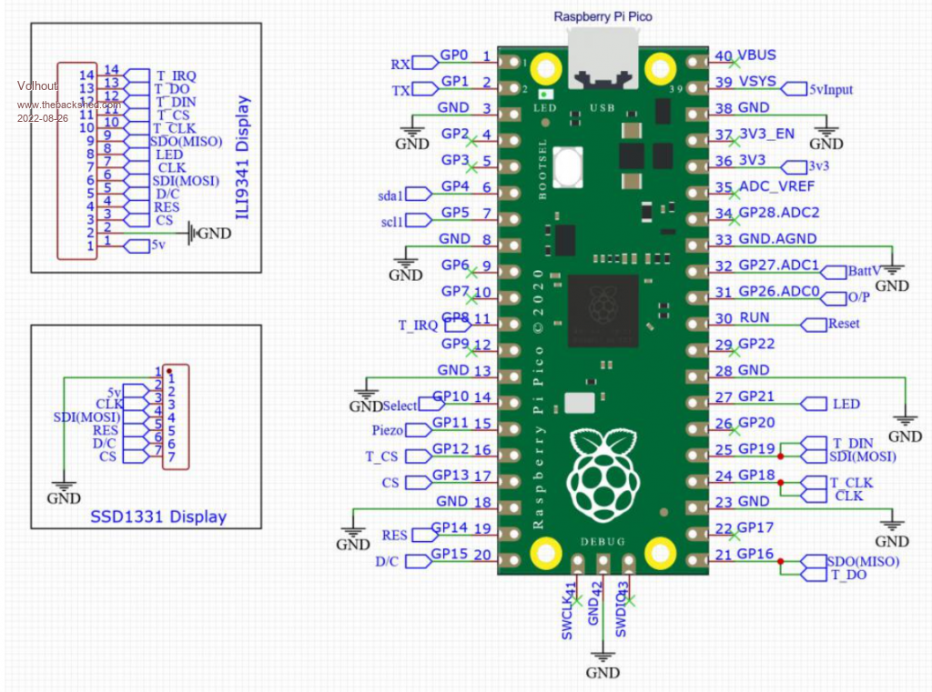 PicomiteVGA PETSCII ROBOTS |
||||
| phil99 Guru Joined: 11/02/2018 Location: AustraliaPosts: 3296 |
From the pin diagram on p 9 of the manual PWM0A COM1 TX I2C SDA SPI RX GP0 1 PWM0B COM1 RX I2C SCL GP1 2 So Pico pin 1, GP0 is Tx - output and Pico pin 2, GP1 is Rx - input It would seem the circuit at the start of this thread is labeled for the destinations of the pins, not the pin function. Diagrams that have actual wires are less confusing. |
||||
| Mixtel90 Guru Joined: 05/10/2019 Location: United KingdomPosts: 8913 |
Specifying GPn pins - never pin numbers - is the best way. That way a design is transferable to any of the Pico clones without modification, no matter how many pins it has or how they are arranged. Showing pin wiring diagrams is pretty but is only applicable to that one model of RP2040-based device. Obviously, this can get a bit out of hand, but if you look at the circuit drawings I produce for my PCBs, you'll see that each "circuit module" is labelled with GPn destinations and the Pico is shown separately. It would be trivial to convert those drawings for *any* RP2040-based module. Mick Zilog Inside! nascom.info for Nascom & Gemini Preliminary MMBasic docs & my PCB designs |
||||
| The Back Shed's forum code is written, and hosted, in Australia. | © JAQ Software 2026 |
