
|
|
Forum Index : Microcontroller and PC projects : Picomite with ssd1963 and touch
| Author | Message | ||||
| matherp Guru Joined: 11/12/2012 Location: United KingdomPosts: 11551 |
How are you powering the SSD1963? If you are using the 3.3V supply from the Pico this could be the problem as the backlight exceeds the Pico current output. |
||||
| stanleyella Guru Joined: 25/06/2022 Location: United KingdomPosts: 2807 |
Some ssd1963 have 5V backlight. If display backlight is 3.3 run from vbus via a resistor? The backlight current must vary though. Those dual 5V and 3.3V breadboard psu supplies are handy. |
||||
| Mixtel90 Guru Joined: 05/10/2019 Location: United KingdomPosts: 8913 |
The backlight on the SSD19633 can be fixed "on", controlled from a PWM pin or controlled via a command from the driver. You simply put 3.3V or 5V on the LED pin and change a SMD link to which you require. It will work fine from 3V3, but not from the 3V3 output from a Pico. Also, you have to be careful with the GND connection on the SSD1963 as the high backlight current can cause voltage drop in pcb tracks and cause problems with the logic supply voltage. Mick Zilog Inside! nascom.info for Nascom & Gemini Preliminary MMBasic docs & my PCB designs |
||||
| TrevorH Senior Member Joined: 06/04/2018 Location: United KingdomPosts: 145 |
The board is powered from a 12v mains PSU with a LM7805 feeding VSYS and 3.3v reg feeding LCD & backlight. It seems as if the sdcard on the display and touch don't like each other. I may try using a separate SD adapter wired to the SPI and see what happens. |
||||
| Mixtel90 Guru Joined: 05/10/2019 Location: United KingdomPosts: 8913 |
Seems odd... Have you tried a different SD card? Also, some displays (I don't know if it applies in this case) have series resistors in the SD card data lines. They tend to introduce problems in some cases. The ILI9341 is like this. Try running a wire from the SSD1963 GND pin back to the incoming supply GND. Also, unless there is already something there, put a couple of caps between SSD GND and SSD 3v3. An electrolytic , say 47 to 100uF, bypassed by 100nF. Edited 2022-09-11 02:02 by Mixtel90 Mick Zilog Inside! nascom.info for Nascom & Gemini Preliminary MMBasic docs & my PCB designs |
||||
| stanleyella Guru Joined: 25/06/2022 Location: United KingdomPosts: 2807 |
The sd card should not matter. It would report no sd card if it worked. The connections in the manual have worked for ssd1306 and ili9341 so I guess are sound for ssd1963. I have a ili9341 that touch is dead and a dead ssd1306 both of which were a waste of time trying but you assume a device is working. Looks like an interesting display in various sizes but expensive. I got my displays 5 years ago,,, inflation :( I also would think there is a common ground that would need no additions and adding caps then I don't know why if the supplies are fine. Some displays do not survive being wired incorrectly and if you still persevere thinking the device is OK then you get nowhere. |
||||
| Mixtel90 Guru Joined: 05/10/2019 Location: United KingdomPosts: 8913 |
The SD card works without Touch. Touch works (after a fashion) without the SD card. As Touch uses an on-board controller, the variable here is the SD card. Will Touch work with the SD card connected but no card inserted? It should do as SD_CS isn't going anywhere. You should just get an error message that there is no SD card. A possibility is that the SD card is doing something odd and not tri-stating the SD signal lines in time, which would result in a bus collision. That's why I asked about trying a different SD card. Note that it's not unusual to have problems when calibrating a touch display. You need to be accurate, get the pressure and timing right on each target and do the whole calibration in a fairly quick time. It happens to all of us. Mick Zilog Inside! nascom.info for Nascom & Gemini Preliminary MMBasic docs & my PCB designs |
||||
| stanleyella Guru Joined: 25/06/2022 Location: United KingdomPosts: 2807 |
The manual says- T_CS Touch Chip Select Recommend Pin 24/GP18 T_IRQ Touch Interrupt Recommend Pin 25/GP19 T_DIN Touch Data In (MOSI) Recommend Pin 15/GP11 T_CLK Touch SPI Clock Recommend Pin 14/GP10 T_DO Touch Data Out (MISO) Recommend Pin 16/GP12 The following table lists the connections required to support the SD card connector: SSD1963 Display Description PicoMite SD_CS SD Card Chip Select Recommend Pin 29/GP22 SD_DIN SD Card Data In (MOSI) Recommend Pin 15/GP11 SD_CLK SD Card SPI Clock Recommend Pin 14/GP10 SD_DO SD Card Data Out (MISO) Recommend Pin 16/GP12 |
||||
| Mixtel90 Guru Joined: 05/10/2019 Location: United KingdomPosts: 8913 |
It does, Stan, but that's not working in this case for some reason. That's why Trevor has split the SDcard away from the same SPI as Touch. @Trevor If you didn't keep a record of the Touch calibration figures then you'll probably have to do it again. Sorry. :( Mick Zilog Inside! nascom.info for Nascom & Gemini Preliminary MMBasic docs & my PCB designs |
||||
| phil99 Guru Joined: 11/02/2018 Location: AustraliaPosts: 3296 |
"I may try using a separate SD adapter wired to the SPI and see what happens." Which type of adapter are you using? The ones with a level shifter IC and 3.3V reg. will often work on the Pico if they have their own SPI bus but work intermittently if at all on a shared bus. To protect the Pico it must be fed from 3.3v not 5v so the SD gets 3V at best. Losses in the level shifter don't help either. For System SPI you want a simple pin-to-pin type. |
||||
Grogster Admin Group Joined: 31/12/2012 Location: New ZealandPosts: 9977 |
This is very odd....  Normally, there are simply zero issues running the SD card and touch on the same SPI channel, as everyone else is saying. I'd also be very interested to know what happens with the original configuration(the one that caused the touch to go nuts), and DON'T insert an SD card as Mick is suggesting. Perhaps it is possible that the SD card is somehow screwing with things as Mick hints at, but that would be extremely rare if that was the case, cos gawd.....the number of people who have built various MM flavours using the SD card and touch on the same SPI port must be up in the hundreds of thousands globally now(if not more), and provided there is no wiring error, they just work!  Watching this thread with much interest, cos you should NOT have to separate out the SD card from the touch. That simply should not be a requirement.  Also, if you can be bothered TrevorH, can you post the details of your chosen SD card. Brand, capacity, format, full-size SD or uSD etc... Smoke makes things work. When the smoke gets out, it stops! |
||||
| stanleyella Guru Joined: 25/06/2022 Location: United KingdomPosts: 2807 |
I would suggest completely rewiring sd card and touch pins to the manual diagram and not assume wiring is correct like I did. Clear all Options.. clear everything and start again. More wires than spi with the parallel data. The screen works? Does GUI CALIBRATE work? Does FILES work? If others have had success with this display and you have not then where is the problem? Wiring errors. Wrong options ie. software setup. Faulty display or faulty pico port due to being grounded for example. I have made simple wiring mistakes that broke working displays :( |
||||
| stanleyella Guru Joined: 25/06/2022 Location: United KingdomPosts: 2807 |
I use these as other pic stuff I do is 5V logic, usually. Bi-direction logic 3.3V logic to 5V logic or 5V logic to 3.3V logic. 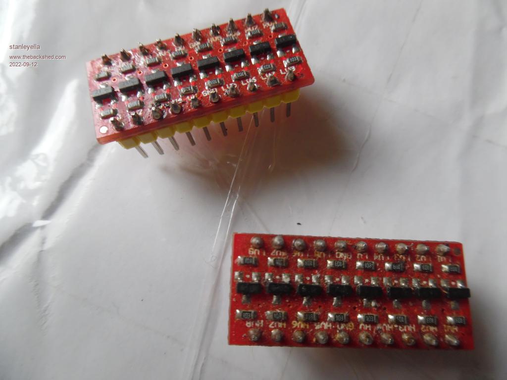 Not needed for pico display. Pics can run at 3.3V, Arduino it slows clock speed. |
||||
| Mixtel90 Guru Joined: 05/10/2019 Location: United KingdomPosts: 8913 |
Even better, simply don't use SD sockets with built-in regulators and level shifters unless you are using them on an Arduino. Stick to straight-through designs (or the ones I've been using that have some 10k pullups and supply decoupling capacitors). All the others with built-in stuff may cause problems, maybe not with your current SD card if you are fortunate, but very likely with a different one. The SD socket on the display should always work unless it's as I said before, one with series resistors on the data lines. Those can be shorted out. The 5" SSD1963 that I have has straight-through connections. Mick Zilog Inside! nascom.info for Nascom & Gemini Preliminary MMBasic docs & my PCB designs |
||||
| stanleyella Guru Joined: 25/06/2022 Location: United KingdomPosts: 2807 |
You can not blame me for testing the sd card reader built into the ili lcd I use, as it is not implemented in the other basic I use and mmbasic does showing/using files good.. It works as an alterative device compared to external sd card reader for anything you would want from sd card,,, even reads rpi os files! I just tested with the first card to hand. When it works it is good but in this case is the manual wrong or the user has made a mistake? If I had a ssd1963 could give better feed back as a user but to much money to buy one and test. |
||||
| TrevorH Senior Member Joined: 06/04/2018 Location: United KingdomPosts: 145 |
Hi, the plot thickens, I've put a separate sdcard breakout board wired to the SPI bus and changed the options back. LCD works OK SD card works OK, If I try to GUI calibrate I get first point OK but touching this causes console to give "Touch not calibrated" repeatedly. only power cycling stops this. Not sure what is happening here, will continue testing. |
||||
| stanleyella Guru Joined: 25/06/2022 Location: United KingdomPosts: 2807 |
If this is resolved, what advantage do parallel data displays have over spi displays in real usage? picomite over clocked and spi display can be fast. Is a parallel port lcd going to be faster in real mmbasic use eg. blit will be faster? I did not think picomite had enough pins :( |
||||
| circuit Guru Joined: 10/01/2016 Location: United KingdomPosts: 305 |
See this post; I had a similar issue with the SSD1963 and Peter replied; https://www.thebackshed.com/Forum/ViewTopic.php?TID=14854&PID=189629#189629#189626 |
||||
| Mixtel90 Guru Joined: 05/10/2019 Location: United KingdomPosts: 8913 |
@Stan Parallel displays are a lot faster to access than SPI because you are shifting several bits of data simultaneously, not one after the other. Yes, blit is faster. It's not MMBasic that slows down access via SPI, it's the limitations of SPI. Note that only the display is accessed as a parallel device, touch and SD are still on a SPI port. Mick Zilog Inside! nascom.info for Nascom & Gemini Preliminary MMBasic docs & my PCB designs |
||||
| stanleyella Guru Joined: 25/06/2022 Location: United KingdomPosts: 2807 |
from @circuit https://www.thebackshed.com/Forum/ViewTopic.php?TID=14854&PID=189629#189629#189626 Maybe lower cpu speed when calibrating and raise after. I do not know the touch controller on ssd9341. XPT2046 on ili getting used to but can be odd on 8bit at 32MHz.. ie does not work hardware spi, software spi must be used..hardware spi works ok on 16MHz.Relevant? I used the free touch pen that came with the lcd and GUI CALIBRATE and said "no errors" and it is precise... for touch. no more real switches/buttons is the plan. |
||||
| The Back Shed's forum code is written, and hosted, in Australia. | © JAQ Software 2026 |
