
|
|
Forum Index : Microcontroller and PC projects : WAVE recording with Picomite possible???
| Author | Message | ||||
| Nimue Guru Joined: 06/08/2020 Location: United KingdomPosts: 427 |
^^ This is important - for me, this is educational only, not attempting to recreate a better way of encoding / decoding data. I'll be happy with the simplest, slowest speed process that can demonstrate encoding a BASIC listing, saving as audio and then decoding. I almost want it to be unreliable and slow as it gives me the opportunity to discuss how and why things need to improve. I see mentioned punch cards -- we had discussed this -- card with eight punched holes and pairs of LEDs / LDRs to read thing in bitwise / bytewise --- Some really interesting suggestions here. Pesky day job getting in the way!! N Entropy is not what it used to be |
||||
| Volhout Guru Joined: 05/03/2018 Location: NetherlandsPosts: 5953 |
About the LM567 It is a PLL tone detector. It has a variable oscillator with centre frequency (set by component values) and a build in tuning range for that frequency, the "lock range". From the datasheet: the maximum lock range for the single LM567 is 14% (typical, maximum 16%). This means that you need worst case 1/0.14=7 cycles to achieve lock, and that is reflected in the attached graph (from the datasheet). 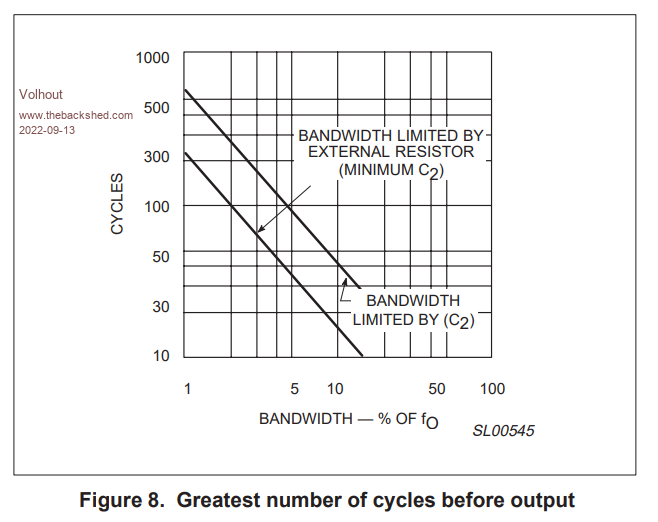 This means that you may have a good chance of detecting 8 cycles of 2400Hz (not guaranteed, but possible), but 4 cycles of 1200Hz is far below what a single LM567 can do. If you narrow the range, it takes even more cycles to lock (detect). There is an application note where they use 2 LM567's each with a 14% lock range, to expand the lock range of the set. 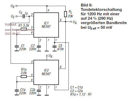 This circuit diagram should fulfill your needs for the 1200Hz detector for FSK cassette tape. Ue is the input (20mV..200mV input voltage, Ua is the digital output, when powered from 5V (Ub) this circuit will output 5V logic). Good luck... Volhout P.S. NE567 and SE567 and LM567 are compatible. Edited 2022-09-13 18:40 by Volhout PicomiteVGA PETSCII ROBOTS |
||||
| Nimue Guru Joined: 06/08/2020 Location: United KingdomPosts: 427 |
DOH!! Using x2 never dawned on me. So, if I use one set up for 1200Hz(1) and one for 2400Hz(0) - with 10 cycles per "bit" with 10 cycles of "silence" between each 1 and 0 -- granted I've just made my own encode / decode protocol, but about as simple as it can be. I could "detect" each on a separate pin or OR (NOR? as it goes low) them together.... Got to do the day job now (sigh). N Entropy is not what it used to be |
||||
| Volhout Guru Joined: 05/03/2018 Location: NetherlandsPosts: 5953 |
I think the silence in between is not needed. Just 1200 and 2400. In advance of any tone there will be silence. If you route both detectors to separate pins you can detect "11" = silence "01" = 1200Hz "10" = 2400Hz "00" is fault Volhout Edited 2022-09-13 20:07 by Volhout PicomiteVGA PETSCII ROBOTS |
||||
| Nimue Guru Joined: 06/08/2020 Location: United KingdomPosts: 427 |
Stop posting interesting things.... Trying to do paid work!! Awesome -- sounds like a plan. N Entropy is not what it used to be |
||||
| Frank N. Furter Guru Joined: 28/05/2012 Location: GermanyPosts: 1123 |
@Volhout: Thank you very much! Can you tell me where you got this "Bild 8"? Frank |
||||
| Volhout Guru Joined: 05/03/2018 Location: NetherlandsPosts: 5953 |
Funkamateur PicomiteVGA PETSCII ROBOTS |
||||
| Frank N. Furter Guru Joined: 28/05/2012 Location: GermanyPosts: 1123 |
@Volhout: Thank you very much!  Frank |
||||
TassyJim Guru Joined: 07/08/2011 Location: AustraliaPosts: 6539 |
A rainy day in paradise so: Kansas City tape read/write I stayed with Basic rather than PIO or CSUB to make it easier to follow what is going on. It does mean that the sending side has to leave gaps between characters to allow for processing time. ' KCTS TassyJim Sep 2022 OPTION EXPLICIT OPTION DEFAULT INTEGER DIM bits(10), message$ DIM FLOAT rxd(200), bt! DIM starttime!, midtime! DIM n, done, k$, char$ CONST bit_time = 3.1 ' should be 3.33 less processing time. CONST char_timeout = 37.0 ' one character takes ~36mS CONST char_time = 12.0 ' at 250k CPU it takes ~10 mS to process one character CONST bit_choice = 1.2 ' this is the time for two cycles half way between 1200 and 2400 Hz CONST dir_mode = 1 ' 1 = sending, 0 = receiving IF dir_mode THEN ' we are sending text message$ = "Hello world" sendtxt message$ PAUSE 2000 DO k$ = INKEY$ IF k$ <> "" THEN sendtxt k$ ENDIF LOOP ELSE ' we are receiving text SETPIN gp15, INTH, startrec SETPIN gp14, DOUT ' used for timing on the CRO DO IF done = 1 THEN ' we have finished receiving a character done = 0 PIN(gp14) = 1 ' used for timing measurements char$ = recchar$() PRINT char$; SETPIN gp15, INTH, startrec ' arm the interrupt ready for the next character PIN(gp14) = 0 ENDIF LOOP ENDIF ' routines used for receiving and decoding KCTS ' parse the array of received timing and extract the 8 bit byte FUNCTION recchar$() LOCAL b, char_asc bt! = bit_time/1.8 ' take the first sample shortly after half way throug it. b = 0 FOR n = 1 TO 100 IF rxd(n) = 0 THEN : EXIT FOR : ENDIF 'print str$(n,5);" ";str$(rxd(n)*1000,6,1);" ";str$((rxd(n)-rxd(n-1))*1000,6,1) IF rxd(n) > bt! THEN IF (rxd(n)-rxd(n-2)) < bit_choice THEN ' we average over two cycles bits(b) = 1 ELSE bits(b) = 0 ENDIF ' print bits(b), (rxd(n)-rxd(n-2)), b, bt! bt! = bt! + bit_time INC b ENDIF NEXT n FOR n = 8 TO 1 STEP -1 char_asc = (char_asc << 1) + bits(n) ' lsb received first NEXT n MATH set 0, rxd() ' finished with it so clear the array recchar$ = CHR$(char_asc) END FUNCTION ' arm the interrupt and timeout ' reset the data array pointer SUB startrec done = 0 n = 1 TIMER = 0 SETTICK char_timeout, stoprec,1 SETPIN gp15, INTH, getdata_int END SUB ' disable interupts and set the done flag SUB stoprec SETPIN gp15, OFF SETTICK 0,0,1 done = 1 END SUB ' get the time of the next cycle and advance the counter SUB getdata_int rxd(n) = TIMER INC n END SUB ' these two subs are all thats needed to send text SUB sendtxt txt$ LOCAL n IF LEN(txt$) > 0 THEN FOR n = 1 TO LEN(txt$) sendchar MID$(txt$,n,1) PAUSE char_time NEXT n ENDIF END SUB SUB sendchar ch$ LOCAL n bits(0) = 0 ' start bit FOR n = 1 TO 8 bits(n) = (ASC(ch$) >>(n-1)) AND 1 ' bits sent lsb first NEXT n bits(9) = 1 ' 2 stop bits bits(10) = 1 FOR n = 0 TO 10 PLAY TONE 1200*(bits(n)+1),1200*(bits(n)+1) ' 0 = 1200, 1 = 2400 PAUSE bit_time NEXT n PLAY STOP END SUB You may have to adjust the pins used to suit your setups. Tested with the picomites running at 250k A bit_time of 3.0 for sending and 3.1 for receiving is reliable on my setup. Set the CONST dir_mode to 1 for sending and 0 for receiving. I used the simple audio filter so there was some 44kHz noise. No effort has been made to streamline any of the functions. The only additional IC is a LM324 op amp configured as a comparator with a bit of hysteresis. It runs happily on 3.3V, noise and all. 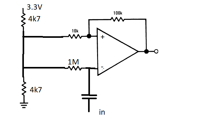 Jim VK7JH MMedit |
||||
| The Back Shed's forum code is written, and hosted, in Australia. | © JAQ Software 2026 |
