
|
|
Forum Index : Microcontroller and PC projects : chage pins for SPI or SD-Card
| Author | Message | ||||
| hhtg1968 Senior Member Joined: 25/05/2023 Location: GermanyPosts: 204 |
seems very cool. i have such sd card adapters... i do not understand the foto (i tried to zoom). the capacitor is between wich points? same for the resistor. can i use the "normal" pins for ground and + from the sd card board after adding capacitor and resisitor? can you create a symbolic explanation or picture? |
||||
| Mixtel90 Guru Joined: 05/10/2019 Location: United KingdomPosts: 8911 |
Peter's standard SD card adapter beats them all for breadboard use. :) Mick Zilog Inside! nascom.info for Nascom & Gemini Preliminary MMBasic docs & my PCB designs |
||||
| paceman Guru Joined: 07/10/2011 Location: AustraliaPosts: 1329 |
I'm using the Catalex SD Card Adapter V1.1 direct to the PicoMite without any changes and it's all working fine. It's powered straight from the USB 5v going into the Pico. The SD module looks identical to the photo in Phill's last post but with the Catalex logo silkscreen. The buffer chip on it is a 14 pin PG8SD and the regulator is an HT1117 3.3. looks like there are two versions 'in the wild' because there was a change in the design back about 2016. Seems the MISO line going back to the Pico had the buffer changed from being connected to Gnd to now being connected to the CS line. That apparently fixed people's issues, see here Greg |
||||
| Mixtel90 Guru Joined: 05/10/2019 Location: United KingdomPosts: 8911 |
[GRUMPY] I don't like that site - it doesn't like my browser (Pale Moon) and I refuse to change to an insecure one simply because they can't write standard, compliant HTML. [/GRUMPY] Mick Zilog Inside! nascom.info for Nascom & Gemini Preliminary MMBasic docs & my PCB designs |
||||
| phil99 Guru Joined: 11/02/2018 Location: AustraliaPosts: 3291 |
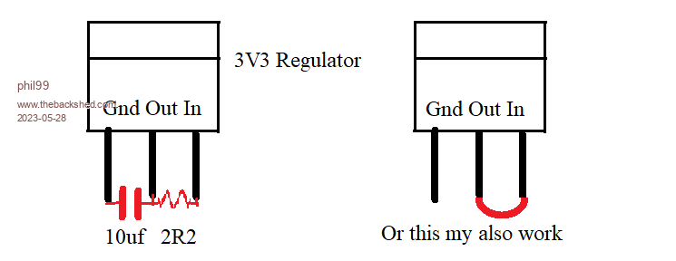 Having 5V on the Pico pins is risky. Bypassing the regulator allows it to be powered from 3V3. The added components filter the supply to the SD card but aren't always needed. Do NOT use 5V with this modification It will destroy the SD card. Use 3V3 supply only. Edited 2023-05-28 18:36 by phil99 |
||||
| IanRogers Senior Member Joined: 09/12/2022 Location: United KingdomPosts: 152 |
Remember I had the exact same problem.. I had to remove the level shifting altogether. Mine however! was only resistors.. Even when I converted to 3v3 it still didn't work.. I'd give my left arm to be ambidextrous |
||||
| Mixtel90 Guru Joined: 05/10/2019 Location: United KingdomPosts: 8911 |
It's a lot of fuss when you only need to solder a bit of male header onto a micro SDcard converter. :) Mick Zilog Inside! nascom.info for Nascom & Gemini Preliminary MMBasic docs & my PCB designs |
||||
| hhtg1968 Senior Member Joined: 25/05/2023 Location: GermanyPosts: 204 |
hi phil99. thank you so much. now - with 3.3v - i feel more secure. |
||||
| The Back Shed's forum code is written, and hosted, in Australia. | © JAQ Software 2026 |
