
|
|
Forum Index : Microcontroller and PC projects : PicoMiteVGA Grey-scale and RGBI output methods.
| Author | Message | ||||
| matherp Guru Joined: 11/12/2012 Location: United KingdomPosts: 11640 |
If you use HDMI you can select the colour palette using the map command |
||||
| Amnesie Guru Joined: 30/06/2020 Location: GermanyPosts: 763 |
Can you please point me to a win 95 palette? If I google it, there a a lot of different and I can't find the correct RGB values. I am sure the original Win 95 pallet is also better than the default PicoMiteVGA, but I will try it! The reason I think even the Win95 colour-pallet is better, is because there are more GREY shades (if I see the correct one).. The main problem with the PicoMite default pallet is the magenta dominance. Edited 2025-02-09 20:32 by Amnesie |
||||
| phil99 Guru Joined: 11/02/2018 Location: AustraliaPosts: 3321 |
First get the desired 24 bit R, G & B byte values for each colour and scale them to 700mV, (ie 127 = 350mV, 255 = 700mv). These are the target values for your resistor network. The input resistance of each VGA colour pin is 75Ω and the output resistance of the Pico pins is around 40 - 50Ω, with a current limit of about 8mA. Apply standard series / parallel resistor arithmetic to get the required voltages on each VGA pin for each colour. With a resistor network that differs from the standard one image will have to be processed to account for the firmware BMP and JPG codec expecting the standard network. My experience is with only 4 bits to work with all you can do is change one kind of wrong to a different kind of wrong. It will always be wrong. |
||||
| Amnesie Guru Joined: 30/06/2020 Location: GermanyPosts: 763 |
Ha! This is cool, that this is now possible with HDMI version, but I will concentrate on the VGA version for now. If Volhout points me to the correct Win95 16 colour-pallet (or I find it earlier) I will use this sunday to definitely hack together this circuit and dither some pictures.  |
||||
| Amnesie Guru Joined: 30/06/2020 Location: GermanyPosts: 763 |
Thank you for this hints and clarification! So I think I stick to Volhouts suggestion with the Win95 pallet, the fact that it can do grey is pretty promising. |
||||
| Volhout Guru Joined: 05/03/2018 Location: NetherlandsPosts: 5994 |
Amnesie, Phil points out an important issue. Build in in mmbasic is a conversion from 24bit rgb, and jpg, to this 16 color palette that is build in as rgb 121. If you change the hardware output, that garbles up the whole picture. All that conversion work has to be re-written. And it is not as simple as the current conversion (stripping bits). You will have to search for the best matching color. Volhout PicomiteVGA PETSCII ROBOTS |
||||
| Amnesie Guru Joined: 30/06/2020 Location: GermanyPosts: 763 |
Volhout, the Windows 16 color palette is great and in my opinion way better than the default PicoMite, see for yourself:  The following pictures are dithered with original Windows 16 colour palette and scaled to fir the PicoMiteVGA max resolution in Mode 3    For me it looks amazing and not that magenta dominance. But the question (@ Volhout) is: does your resistor network, which you posted earlier, work for this (win 16 colour) palette? If so, I will definitely give it a try. I don't really understand what you mean with: Hm.. I am just a bit confused, because you initially wrote that with your resistor network it is easy to adapt?! I don't care if the colour-names are not the same, for example if I print a text and I do use "rgb(red)" and with this new palette there is no "red" behind this word but (for example blue)... This is not a problem... I added again the original pictures in archive, since the forum software compresses them: windows16_color.zip Greetings Daniel Edited 2025-02-09 22:10 by Amnesie |
||||
| Amnesie Guru Joined: 30/06/2020 Location: GermanyPosts: 763 |
@ Volhout I just soldered your resistor network together & it works perfect, in fact I like it so much I will design a switchable option on my PCB to choose between default and windows 16 color palette! Thank you!  Here are some real pictures, as you can see: even in the editor one can see the colors perfectly! I love the option of having grey! This was really easy to solder. just adding two more resistors and changing two values. 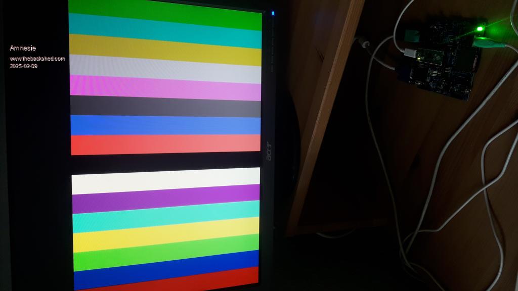 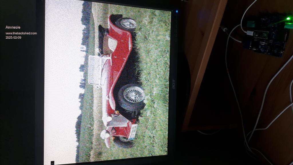 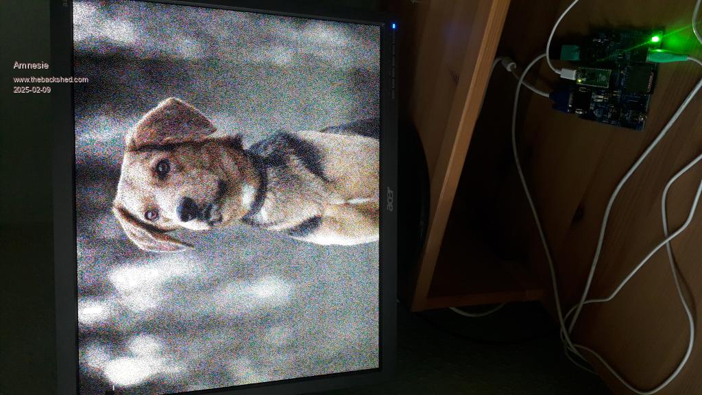  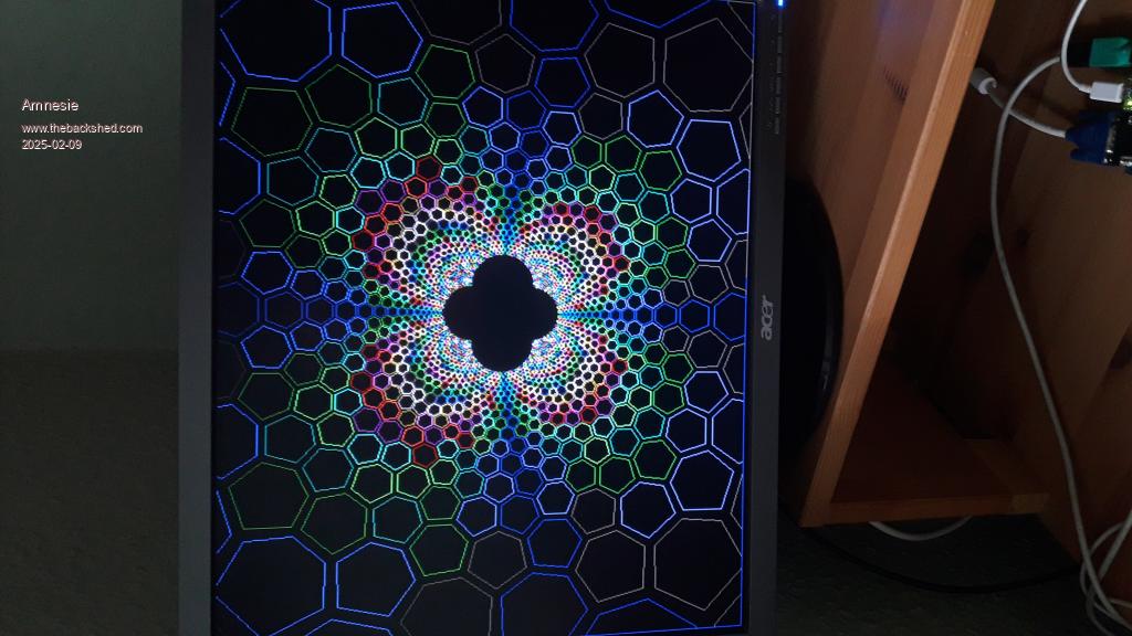 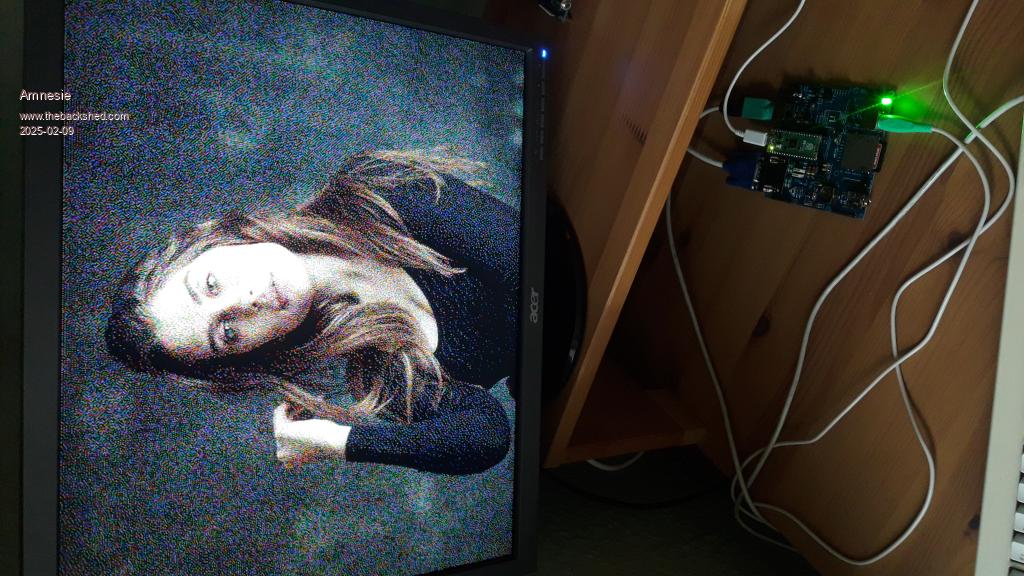 |
||||
| Volhout Guru Joined: 05/03/2018 Location: NetherlandsPosts: 5994 |
Hi Daniel When PicoMite VGA is loading a 24 bit RGB picture from SD card it does following Red Green Blue 7 6 5 4 3 2 1 0 7 6 5 4 3 2 1 0 7 6 5 4 3 2 1 0 | | | | +-----------------R G G B-------------+ This is the way it creates RGB121 from RGB888. It is not dithering, it is extracting. When you have RGB1111 you should also look at the Red bit 6 and Blue bit 6 to determine the closest matching rgb1111 color. This is called dithering (find the closest color). And with algorithms like Floyd (-or- "Apple"), you try to compensate the remaining mismatch in surrounding pixels (i.e. this pixel is a bit too red, let's try to find a color that is slightly less red in the adjacent pixels). Extraction may cause more noise than dithering. I think this also shows in the diference in noise level in your photo's from the actual screen, and the PC ditherings. Volhout P.S. I am not sure how this works on HDMI. When you set a color map, does it use this color map to create the 16 colors from an 24 bit RGB file on disk ? That would also require dithering. I guess it only works at output of pixels. Peter ? Edited 2025-02-10 02:10 by Volhout PicomiteVGA PETSCII ROBOTS |
||||
| Amnesie Guru Joined: 30/06/2020 Location: GermanyPosts: 763 |
@ Volhout: thanks for this explanation. But I converted the pictures before hand with respect to the windows 95 color palette. The picture only consists of those 16 colors. I used the free online dithering tool: https://doodad.dev/dither-me-this/ and defined those 16 colors. Does that mean even if they are dithered, they are not? Just to be clear, I have not just put an normal image to the SD card and loaded it (!) I dithered it before. Anyways, for me it works really good and I like this palette way more than the default one on the PicoMite (waaaay to much magenta and no grey). Greetings Daniel |
||||
| matherp Guru Joined: 11/12/2012 Location: United KingdomPosts: 11640 |
In HDMI 640x480 the output is RGB555. For any of the modes (except mode 4 which is RGB555) you can specify which RGB555 colour maps to any RGB121 or RGB332 colour. So in mode 2 and 3 you have 16 "colours" available which can each be set to any of the RGB555 colour space. In mode 5 you have 256 colours to match to RGB555. Someone wrote a program which would take a 4-bit colour BMP file and set the requisite map to display it in the correct colours as defined in the BMP look-up tabele. For 1024x768 and 1280x720 modes the output is RGB332 so modes 2 and 3 can map to 256 available colours |
||||
| phil99 Guru Joined: 11/02/2018 Location: AustraliaPosts: 3321 |
@Amnesie Here are the RGB values extracted from your Windows 16 color palette image. Top row &H 00 00 00, 00 00 80, 00 80 00, 00 80 80, 80 00 00, 80 00 80, 80 80 00, C0 C0 C0 Bottom &H 80 80 80, 00 00 FF, 00 FF 00, 00 FF FF, FF 00 00, FF 00 FF, FF FF 00, FF FF FF A colour converter program for MMB4W for images with that palette. It extracts the Intensity value from the image and puts it in the green LSB of a RGB(1,2,1) version of the image for the Pico 121 codec to display through the RGIB resistor network. It's a rough as guts but it shows what to do in a proper program. Runs on MMB4W. 'Converting RGB(8,8,8) to Windows 16 color palette for RGIB(1,1,1,1) hardware. 'for display through RGB(1,2,1) codec on RGIB(1,1,1,1) hardware 'using Green low bit (GP19) for Intensity control 'MMB4W uses RGB(B,G,R) which is confusing!!!!!!!!!!!!!!! 'Load an image to the screen before starting set its width and height (pixels) here. Dim integer Width = 320, Height = 240, TopLeftCorner = 200 'Change the input and output file names to suit 'load bmp "E:/MMBasic4W/W_16_color_p.bmp",0,TopLeftCorner load bmp "E:/MMBasic4W/wallaby.bmp",0,TopLeftCorner 'source image 'load bmp "E:/MMBasic4W/W_16_color_p.bmp",0,TopLeftCorner+300 load bmp "E:/MMBasic4W/wallaby.bmp",0,TopLeftCorner+300 'again for comparison Dim integer R, G, I, B, X, Y, G6=2^6, G7=2^7 For Y = TopLeftCorner To TopLeftCorner+Height : For X = 0 To Width B = (Pixel(X,Y)>>16) and 255 'extract the colours G = (Pixel(X,Y)>>8) And 255 'MMB4W Pixel() returns 32 bit TBGR R = Pixel(X,Y) And 255 If R>192 or G>192 or B>192 Then :I=G6:Else : I= 0 : EndIf 'find the Intensity If R > 127 Then : R = 255 : Else : R = 0 : EndIf 'convert red to 1 bit If B > 127 Then : B = 255 : Else : B = 0 : EndIf 'convert blue to 1 bit If G > 127 Then : G = G7 : Else : G = 0 : EndIf 'convert to G MSBit Inc G,I 'and add Intensity to G LSBit If G = 192 Then G = 255 Pixel X,Y,RGB(R,G,B) 'Colours also reversed here if a single 24 bit number is used next : next save image "E:/MMBasic4W/16_colour_RGIB_out.bmp",0,TopLeftCorner,320,240 End 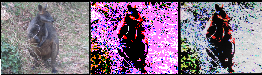 Original Wallaby image, After processing on MMB4W, Photo of PicoVGA monitor Edit. Just noticed the monitor pic was from before I found red and blue are transposed in Pixel() in MMB4W. It now looks a bit better than that, a slightly darker version of the pic on page 1. As Peter said HDMI will give a better result. Edited 2025-02-11 10:28 by phil99 |
||||
| phil99 Guru Joined: 11/02/2018 Location: AustraliaPosts: 3321 |
Here are the measured VGA voltages compared with the Windows 16 colour palette voltages. In the last column there is a Schottky diode in series with the 330Ω resistor. The resistors are driven by Pico pins so actual pin resistance is included. Colour Ideal 390Ω & 820Ω 330Ω & 1kΩ 330Ω+diode & 1kΩ value Voltage mV Voltage mV Voltage mV Voltage mV &H00 0 0 0 0 &H80 351 236 186 230 &HC0 527 470 548 504 &HFF 700 702 731 691 None of them is exact but the visible difference is modest. |
||||
| Amnesie Guru Joined: 30/06/2020 Location: GermanyPosts: 763 |
Hello phil99, thank you for explaining how to conversion works with your program! But I am a bit surprised that you results are (in my opinion) not that good as if I use the dithering method with that colour palette via this website: https://doodad.dev/dither-me-this/ Of course my images have got more noise, but on my posted pictures here this is a bit of an over-exaggeration due to the size of the monitor and camera. If I load that image on a 2,8" TFT it looks great. But my whole point isn't really about better looking images (though I find this colour palette WAY BETTER than the original default one), but more about having the original windows 16 colour palette as an option for GUIs). Now I have grey, which is important for me for GUI stuff. I already designed my PCB to allow switching between default & win 16 colour. It is just a "nice to have", especially for my applications. You created a different resistor network (schottky etc.) than Volhout. But for my eyes Volhouts resistor network works just perfect - can you tell me if there is a problem with it when it comes to voltages? Is it "unsafe", so that I have to redesign my PCB? Or is your version just a hint more accurate?  Greetings Daniel |
||||
| phil99 Guru Joined: 11/02/2018 Location: AustraliaPosts: 3321 |
1) What the table shows is that a simple resistor network, even if variable resistors were used, can't exactly reproduce the Windows 16 colour palette. A more complex design using transistors would be needed to do that. Like the one near the bottom of the previous page in reply to @Hawk. However near enough is good enough. If it were perfect you would still only have 16 correct colours out of 2^24 that could be in an image. 2) 'Is it "unsafe", so that I have to redesign my PCB?' No, the minimum "safe" resistance the Pico pins can drive is about 270Ω. It is just a matter of which one looks best to you. 3) The 2.8" LCD uses 16 bit colour - RGB(5,6,5) so can accurately reproduce the Windows 16 colour palette. From this you can see producing the Windows 16 colour palette in RGB format needs 4 values per colour, &H00, 80, C0, FF or RGB(2,2,2) The only way the PicoVGA can reproduce the Windows 16 colour palette is with an Intensity bit, which it does not have. It has a second green bit instead. Images are processed through a RGB(1,2,1) codec that can't read the intensity. The purpose of the converter program is to get the Intensity values from the image and replace the green low bits with them - RGIB(1,1,1,1) which the resistor network combines to get close to the correct RGB VGA voltages. Without it green low is modulating all the colours, without regard to the required intensity. 4) You can still use dithering in combination with the converter. Try both dithering before conversion and vice versa to see which is best. . Edited 2025-02-12 08:07 by phil99 Footnote added 2025-02-12 10:33 by phil99 Re point 4). Dithering should be done before converting to RGIB. If done after it will treat the I bit as if it were green. |
||||
| Amnesie Guru Joined: 30/06/2020 Location: GermanyPosts: 763 |
Thank you for this extremely interesting explanation! This brings a bit more light into this topic. I've also tried your suggested (or mentioned) resistor network(s) above and have to admit, that I can't really see any difference, or let's say they are barely visible. I just leave it as is on my PCB. But now I know, thanks to your explanation, that for a real windows 16 color palette, a little more effort is necessary. But as said, with the resistor network I copied from Volhout, I am satisfied 100% and having different grey values is a huge help form me designing proper GUI stuff. EDIT: "proper GUI stuff" .. I mean this always depends on what one prefers of course  Now it is switchable .. so I have both :) Now it is switchable .. so I have both :)So thank you all :) Greetings Daniel Edited 2025-02-12 08:14 by Amnesie |
||||
| The Back Shed's forum code is written, and hosted, in Australia. | © JAQ Software 2026 |
