
|
|
Forum Index : Electronics : Good money after bad - Solar upgrade time
| Author | Message | ||||
| oreo Senior Member Joined: 11/12/2020 Location: CanadaPosts: 133 |
So in order to charge my batteries, I need about 82v and I have 8 hours each night at the lowest hydro rate. So I figured that I needed about 2kw. So I purchased these power supplies. 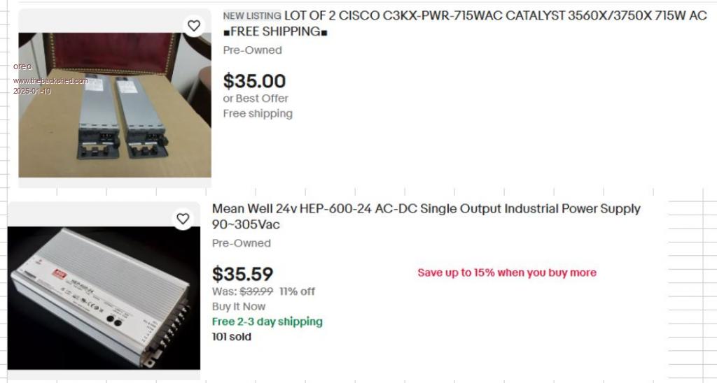 The HEP600-24 can be adjusted up to about 26v, is ~95% efficient and has an adjustable current limit from 12-25amps. The C3KX-PWR-715WAC is 56v, 12.5A and is about 88% efficient. A better choice would have been the PWR-C1-715WAC-P which has the same rating, but with platinum efficiency (94%). So I have the 2 56 volt power supplies feeding into .025ohm resistors into the 24v supply (so the 56v units share the current) feeding into a schotkey diode to ensure the battery does not back feed into the power supplies. I stuck it into a old inverter box and put in a Voltage/current/power measuring meter. 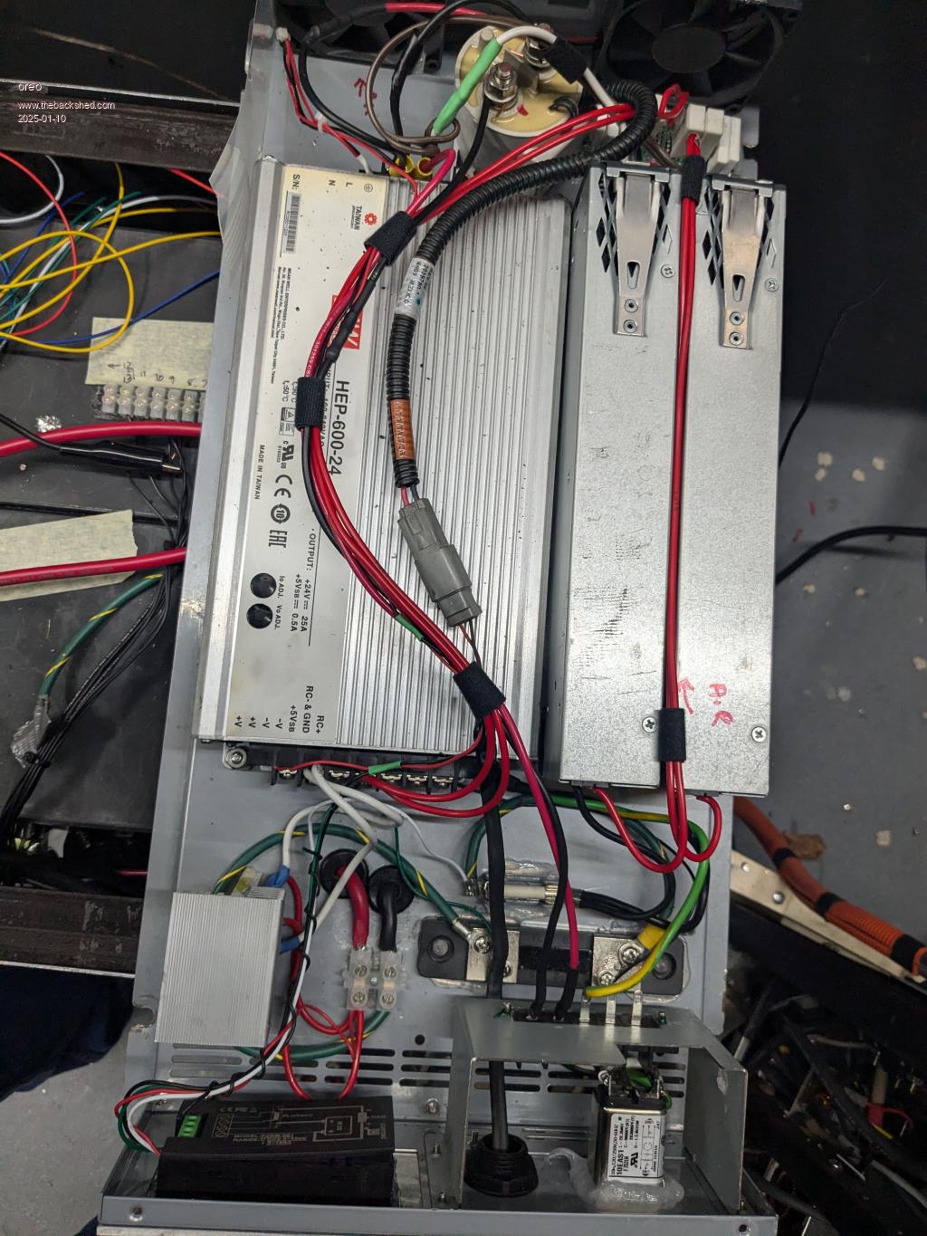 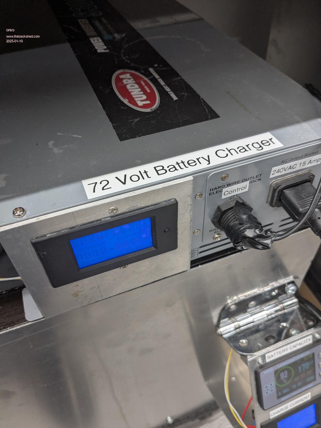 It works well, and right now I have it charging at 20amps and have it controlled with a mechanical timer. I will get more resourceful in time with this. Some other interesting power supplies which at times can be purchased cost effectively. (12v server power supplies like the HP one below are really cheap) 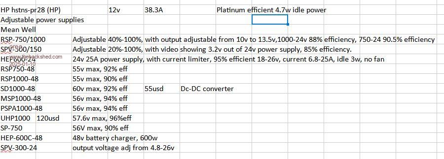 This website has data on the efficiency of many different power supplies You can download the whole list into a spreadsheet. Power supply efficiency numbers Greg |
||||
| oreo Senior Member Joined: 11/12/2020 Location: CanadaPosts: 133 |
I also use these bench supplies for charging the main battery during testing etc. 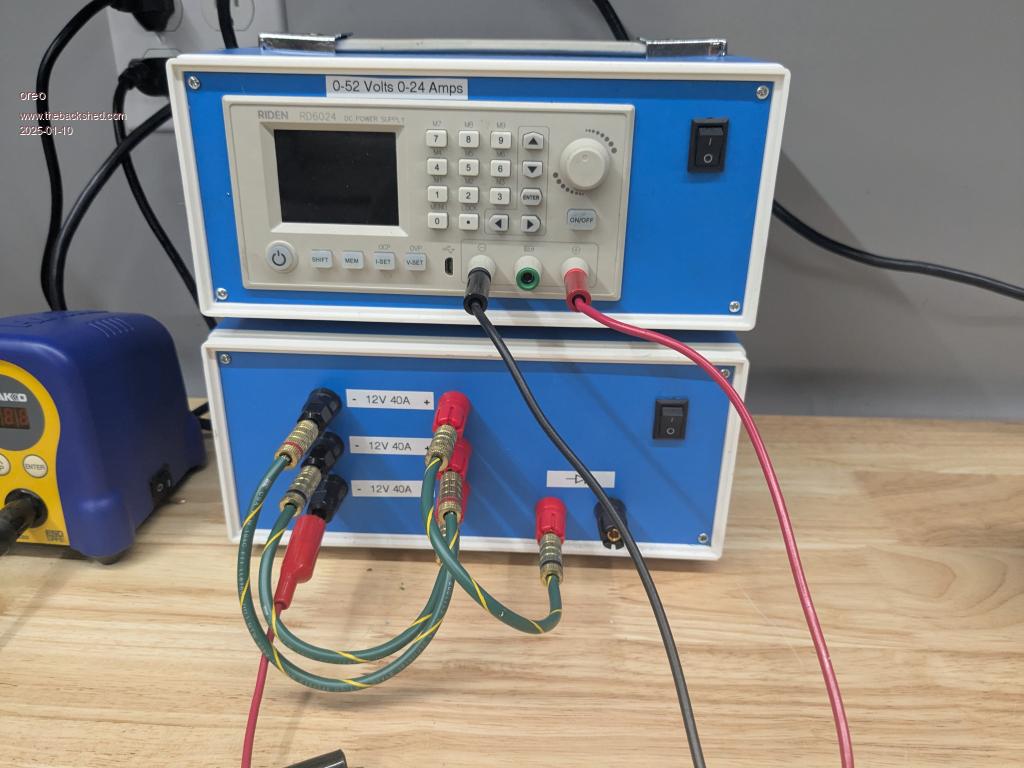 The upper supply uses 1pc of C3KX-PWR-715WAC, while the bottom supply uses 3pcs of HP HSTNS-PR28. The project cases are from amazon, and while they are made with the thinnest of materials, everything seems to be just ok. 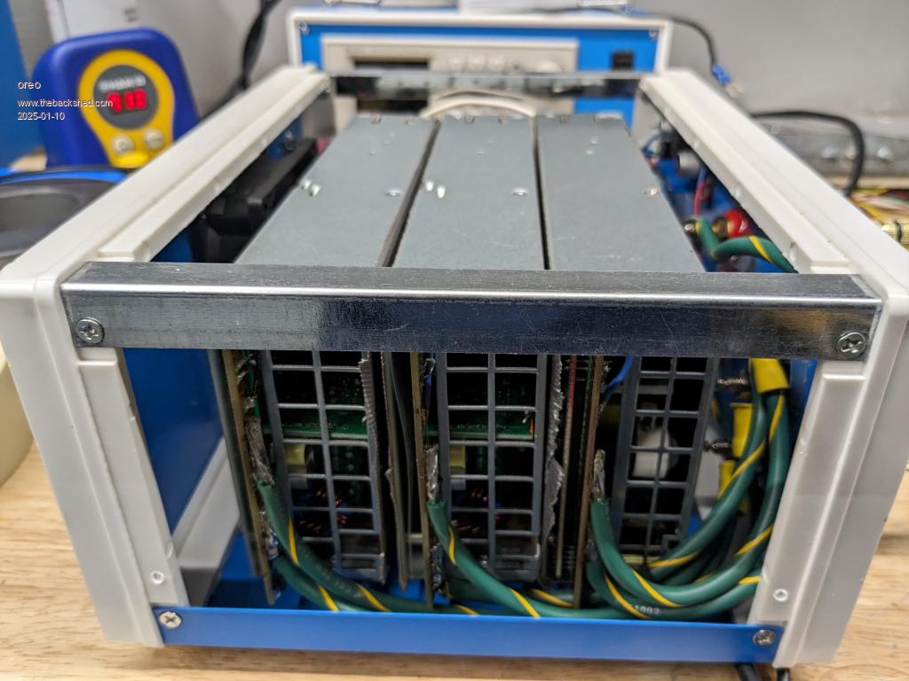 Unfortunately these HP 12v power supplies connect the gnd of the supply to the case, and also have a few caps running from the 240v line back to the case. So you need to remove the connection to the case and the caps for all but 1 of the supplies. Greg |
||||
| oreo Senior Member Joined: 11/12/2020 Location: CanadaPosts: 133 |
So I packaged the second battery. This gives me about 14-15kwh to play with in total. This is prior to adding the covers 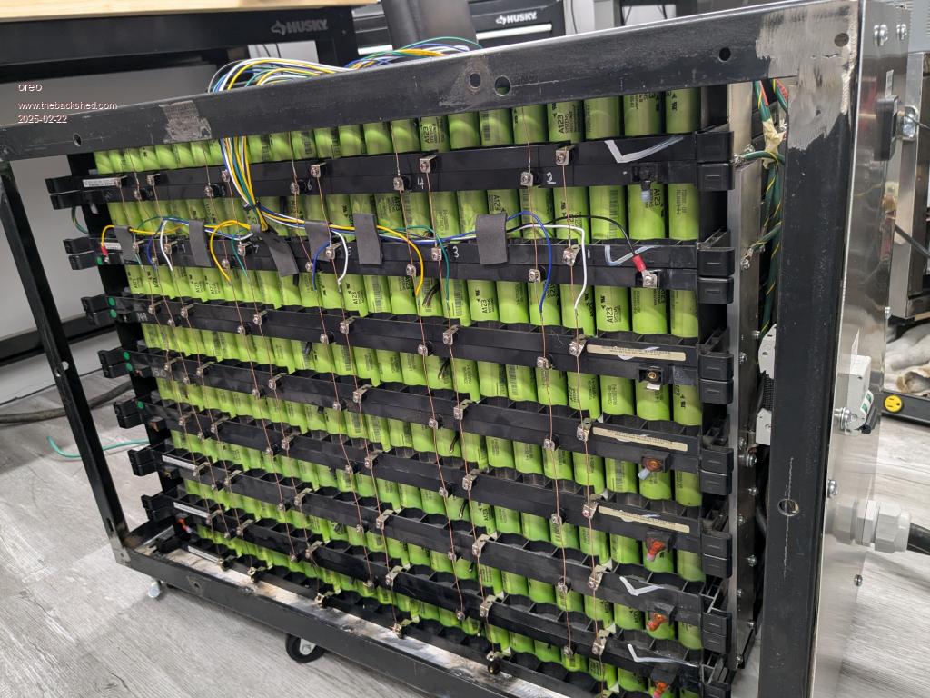 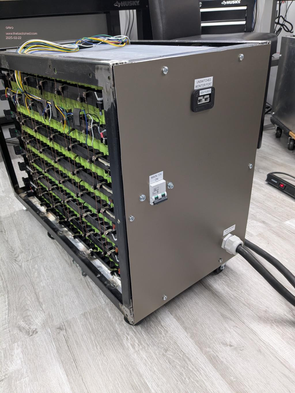 And I ended up getting a used automatic transfer switch. It's really designed to be used with a generator, but I changed that up so that if solar dies, after a minute the switch connects to utility. I have to manually move the switch back to solar should it trip. This way if there is a failure when I am away, everything will continue to run. So far I have moved about 14 circuits over to solar, using breakers in the ATS. 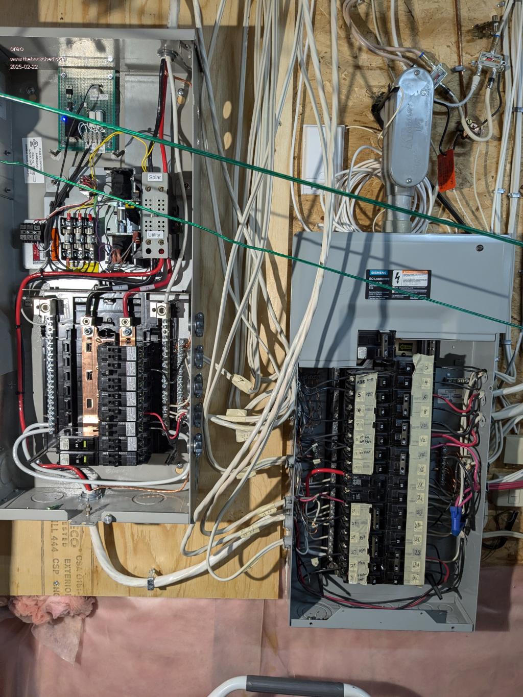 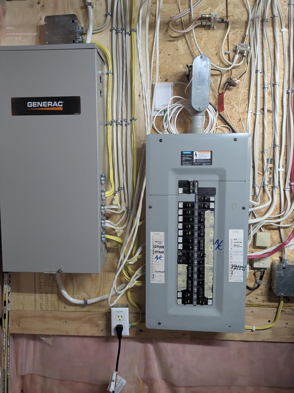 Greg |
||||
Revlac Guru Joined: 31/12/2016 Location: AustraliaPosts: 1285 |
Quite an impressive battery build.  Cheers Aaron Off The Grid |
||||
| oreo Senior Member Joined: 11/12/2020 Location: CanadaPosts: 133 |
^thanks Aaron. I do wish the packs I am using were smaller. These batteries take up a lot of room. Greg |
||||
| oreo Senior Member Joined: 11/12/2020 Location: CanadaPosts: 133 |
So I just had my first major explosion. Actually it was pretty muted, with not even any FET packages getting blown off. Not sure what happened, although it was running at about 6kw for an extended time. Half the FETs, one driver transistor, the 8010 chip, the 80-12v DC-DC converter and 1 voltage comparator were all sent to the promised land. Surprisingly the 8010 and voltage comparator were being powered off 5v and the 5v regulator was still outputting 5v. I replaced the 5v regulator, "because". This gave me the opportunity to fix some things I had been putting off. 1. When I built this inverter board 5 years ago I didn't use particularly good substitutes for the TIP41/42's. I had purchased some TIP41/42's so I upgraded those. 2. I didn't document the additional windings I put on my donor transformer, and also had mistakenly used the wrong gauge wire (smaller) on some additional HV windings I added to it. This was fixed along with adding more isolation tape between the HV and LV windings. The transformer is now slightly quieter, and the HV winding resistance is now 10% lower. The transformer still weighs in at 35lb, and I have an additional transformer that I plan to make these modifications to. 3. I had ordered some MS225060-2 cores off EBAY so I could rewind my inductors. The vendor ended up shipping me MS184040-2 cores and indicated they actually did not have the correct core in stock. These cores were not really going to be much better than what I already had, but ended up building 2 replacements. They are in series with each winding, and each has the same equivalent wire gauge, but 1 is built with multiple 20awg windings while one is built with normal stranded welding cable. We will see what measurable difference in temperature there is during operation. So everything is back up and running... .jpg) 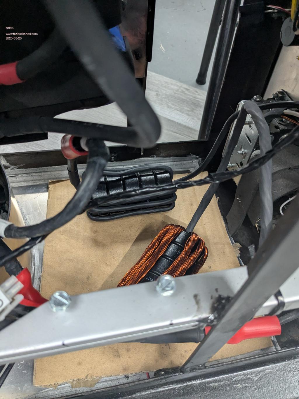 Greg |
||||
| oreo Senior Member Joined: 11/12/2020 Location: CanadaPosts: 133 |
A care package arrived yesterday. Wiseguy's power board and Nano drive system. 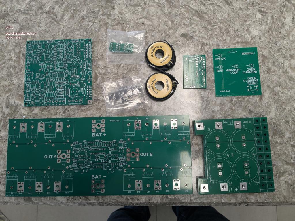 Thanks again Mike, everything arrived in perfect condition! Greg |
||||
| oreo Senior Member Joined: 11/12/2020 Location: CanadaPosts: 133 |
So I have the boards built up, and have been doing some testing. First off I have to comment on what a fantastic job Wiseguy, Keepis and Poida have done on this project.  The components fit perfectly into the pcb and the design is robust(from others). The documentation is fantastic and makes it pretty straight forward to get a system together. The software is complete and the terminal program is slick. Very well done, and I thank you! Picture before power FET's were added 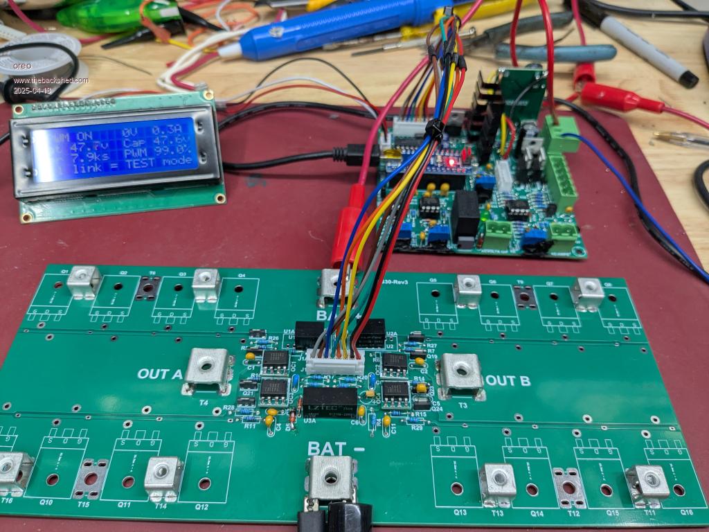 So before I connect this to a transformer, I thought I would run some measurements by those who know, to confirm they appear to be in line. Waveforms on the output look good, and everything seems to be fine, except the standby power seems to be higher that I was thinking it would be. 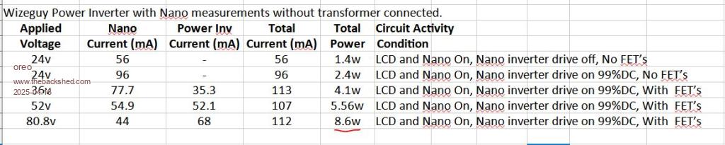 I tried increasing the dead time by adding a 470pF in parallel with the 1n5 capacitors, tried switching back from 60Hz to 50hz and these numbers did not change. Also, with 80v on the output FET's and with the inverter off, there is no leakage. So is this expected and I am good to go, or does it seem there is a problem? thanks! Greg |
||||
| poida Guru Joined: 02/02/2017 Location: AustraliaPosts: 1480 |
these low power levels when running are why we do this. every Joule we get from the panels needs to be spent well. oh, and Wiseguy is a proper and excellent E.E. with a lifetime of experience in power electronics. He gets it right alright. wronger than a phone book full of wrong phone numbers |
||||
| wiseguy Guru Joined: 21/06/2018 Location: AustraliaPosts: 1297 |
Thanks for the vote of confidence Poida - like the rest of us I try hard.... Greg, the idling power looks a bit high to me with no transformer connected. It might be ok but I am concerned enough to build up the new Rev3 power board (mine is at Rev2). All the orders for new boards get the enhancements (I hope...) where as I usually have the previous Rev. Maybe I need to prove the Rev3 design changes and build one up to test on the same platform. A major difference is that you are running off 80 volts and the switching frequency running at 100% SPWM with the higher input voltage and the FETs inherent output capacitance will all have an effect to draw more current but I have not done any calcs to give me a ballpark figure, but it feels a bit high. What FETs are you using again please ? Did you use separate ferrite beads on the FET Drains? Also having the test capacitor PCBs fitted might help, I suggest the Cap boards have one 220u - 470u 100V capacitor board fitted, at this early stage. It is probably ok but I suggest holding off from attaching a choke/transformer for a day or two until I catch up with you and can confirm your results. Bad timing - I am in the middle of a bathroom renovation at a different location (contracted out) so supervising only. Edited 2025-04-14 19:51 by wiseguy If at first you dont succeed, I suggest you avoid sky diving.... Cheers Mike |
||||
| KeepIS Guru Joined: 13/10/2014 Location: AustraliaPosts: 2197 |
If this has been mentioned before then please ignore me, but just in case someone is wondering, the % of SPWM drive will always be at 99% as the Controller can't regulate SPWM without AC feedback, it's limited to 99% (thank Poida) for obvious reasons . Edited 2025-04-14 19:53 by KeepIS NANO:Inverter V 8.2ks - Linux AvrDude GUI script V4.1 |
||||
| oreo Senior Member Joined: 11/12/2020 Location: CanadaPosts: 133 |
Mike, I used Silup SP012N02AGHTF's. SP012N02AGHTF I already added the CAP boards with 560uF caps. I was trying to measure some waveforms with the scope and it was way too noisy without some capacitance in there. This made no difference to the idle power. Yes, I did use ferrite beads, but in a non standard way to allow a mechanical layout without using the bars of aluminum under the FET's. I used these beads Fair-Rite 2643022401 trimmed to 4.2mm in length and then necked down the center lead on the power FETs. I properly grounded the leads on the FETs when doing this. I also used 1/4WS resistors, which are a 1/4w resistor in a 1/8w package.This Style This allows the board to be mounted to a flat plate/heatsink. 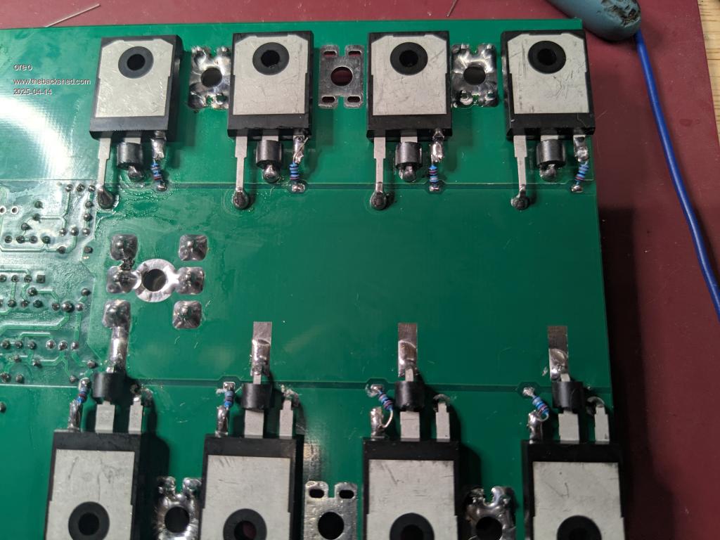 Thank you for looking at this Mike! No issue standing by. Greg |
||||
| oreo Senior Member Joined: 11/12/2020 Location: CanadaPosts: 133 |
So I realized this morning, that I could do some additional testing on my second power board. So I installed just 1 set of FETs (vs 4) in this second board and retested at 80v. I then barnacled a second FET (RS135N170's) in parallel with the original SP012N02AGHTF's. (no ferrite bead, and shared gate resistor) So, with with a single set of SP012N02AGHTF's installed, the power drawn by the power board was exactly 1/4 (18mA) of when 4 were installed. I let it run for a bit, and all the FET's tracked each other temperature wise (about a 10C rise) 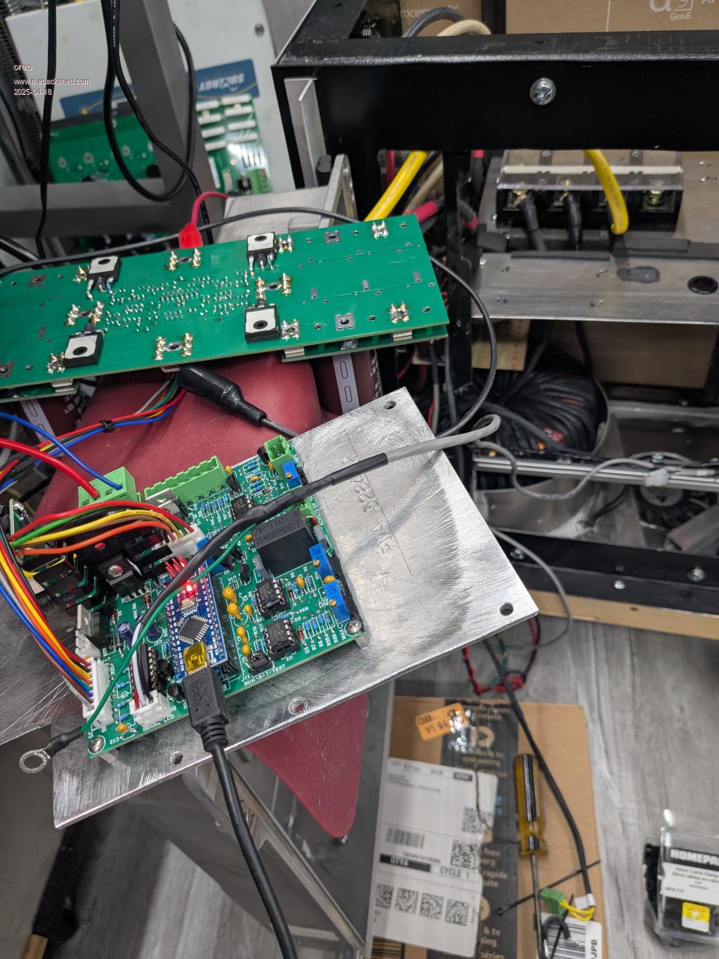 I then barnacled a second similarly rated TO220 packaged fet beside the original, and perhaps because there was no bead, or gate resistor, the current went up by 24mA 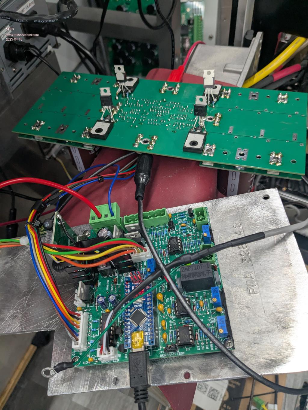 Greg |
||||
| nickskethisniks Guru Joined: 17/10/2017 Location: BelgiumPosts: 481 |
Damn, was writing a long post and then I was kicked out and lost my post...  Long story short, I did some datasheet reading including your mosfet used, turns out you are aiming some what higher for input voltage then most of us. So, I found out mosfet characteristics get "worse" quite fast when going up in Vds rating, not a real surprise, right? Compared to a Irfp4568 just for a equivalent comparison, your mosfet turns out really good on first side, but given the information in the datasheet is somewhat light compared to the infineon brand I would be carefull. Also specs are given for only 20A compared to the 100A infineon is using. It would be interesting to compare other higher voltage mosfets in your circuit, but I don't know if this is your intention. As Wiseguy pointed out, the output capacitance is one factor of a mosfet, an other one is the mosfets body diode, it is important in our circuit and with higher Vds they get slower and also hold a higher Qrr wich increases these no load current. Although your Coss is lower compared to the HY5608 it turns out the Qrr is 10times higher. Don't really know how specifications are off under "no load" compared to datasheet numbers "under load". So it might still be difficult to interpret if someone comes with numbers of an other mosfet. Everything gets worse when using higher voltage although your current draw will not be so high as ours. I have the feeling your loss could actually be just normal. The mosfet could be well suited for your circuit, but it might be worthwhile to investigate some other mosfets, I personally would be careful with these less known companies. Edited 2025-04-18 05:58 by nickskethisniks |
||||
| oreo Senior Member Joined: 11/12/2020 Location: CanadaPosts: 133 |
Yes, this has happened to most of us. What I have noticed, is that even though you are actively typing a response, the website logs you off after a period. You can still preview your post, and everything looks to be working properly, but once you hit "save post" you have lost everything. What I do now, is open a new window and check to make sure I am still logged in. If not, then I log in again, prior to hitting the "save post" button. Yes, originally I was looking to purchase HY5012W's, but couldn't get stock from LCSC. The spec's of the FET I am using looked similar, but yes I noticed that at times the specification was listed at a lower voltage or current than I was interested in. I am not too concerned at this point at the extra losses at idle, I was just confirming that something else was not wrong. The issue with selecting a different part is knowing what the important specifications are. The Infineon part you mentioned has comparatively low SOA current and Avalanche rating which may or may not be an issue. Greg |
||||
| KeepIS Guru Joined: 13/10/2014 Location: AustraliaPosts: 2197 |
I just powered the Test Unit without the Toriod connected and measured the total current as per your setup. 52v = 147mA. 7.6 watts no Toroid - Electronics, LCD and regulator power. 52v @ 340mA. 17.7 watts - Running Inverter (with Toroid) Idle power. The Toroid generating 240Vac output added 10.1 watts . Edited 2025-04-18 11:01 by KeepIS NANO:Inverter V 8.2ks - Linux AvrDude GUI script V4.1 |
||||
| oreo Senior Member Joined: 11/12/2020 Location: CanadaPosts: 133 |
Thank you very much for doing this KeepIS! So from your numbers my measurements are in line with what is to be expected. That is excellent news.. Greg |
||||
| oreo Senior Member Joined: 11/12/2020 Location: CanadaPosts: 133 |
It's Alive! Got the boards mounted and went through test and finally power up. I have only tested it with a 1.5kw load, but need to get the current sensing working (right now the current stays at 3.2A regardless of draw) prior to pushing it harder. So I knew I was going to have troubles stuffing these new boards into my current inverter chassis. Luckily I recently picked up an scrap solar inverter that has a large cast bucket with fins on it. Cast aluminum does not conduct heat as well as an extrusion, so we will see how it goes. The assembly has hinges, so I can open it for service. 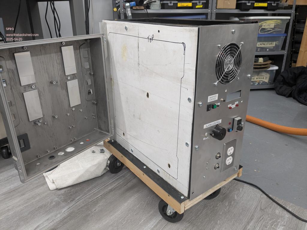 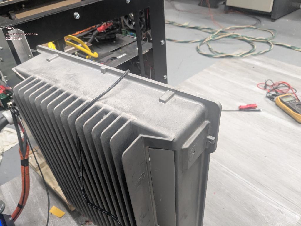 I mounted the Nano at the bottom of the chassis/heatsink. I used a DC-DC for the 80-12v conversion. 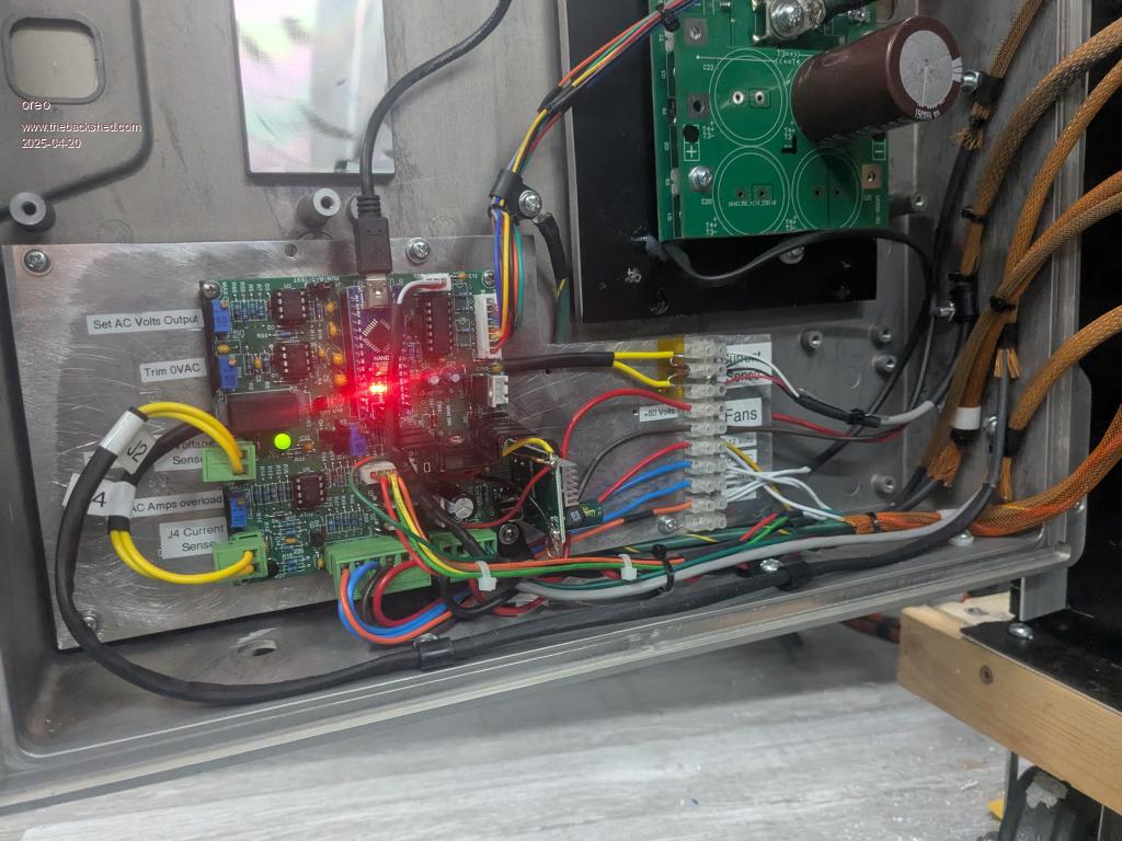 And the power board at the top. (of course for heat transfer it would have been better to reverse this, but the chassis/heatsink was not built to facilitate this) Note the isolated DC-DC converter on the upper shelf used to drive the fans. I have 3 24v fans which are rated at .76amps each. I will adjust the voltage/current once I understand how much cooling I need. 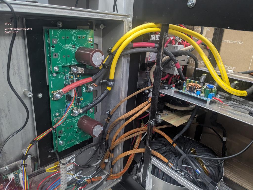 Front of Unit -I am only using the green led from Nano. Alarm and Battery controls are currently disconnected. 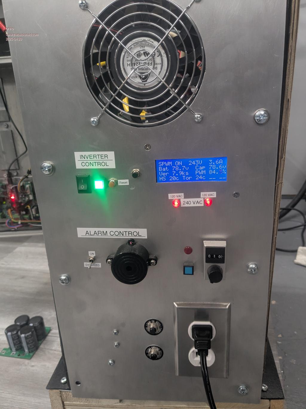 Rear of Unit. Manual charging of capacitors being used. 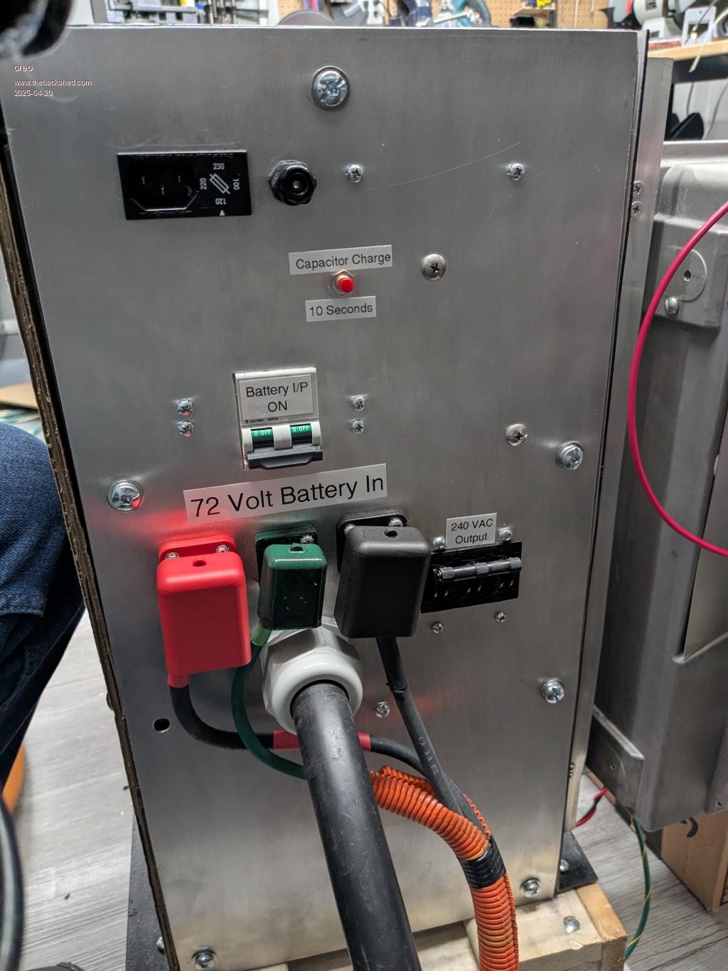 This top shelf is where the inverter used to sit. I need to rethink inductors. Oh, and one side of the cabinet is made of cardboard. I need to cut and drill and paint a real part soon. 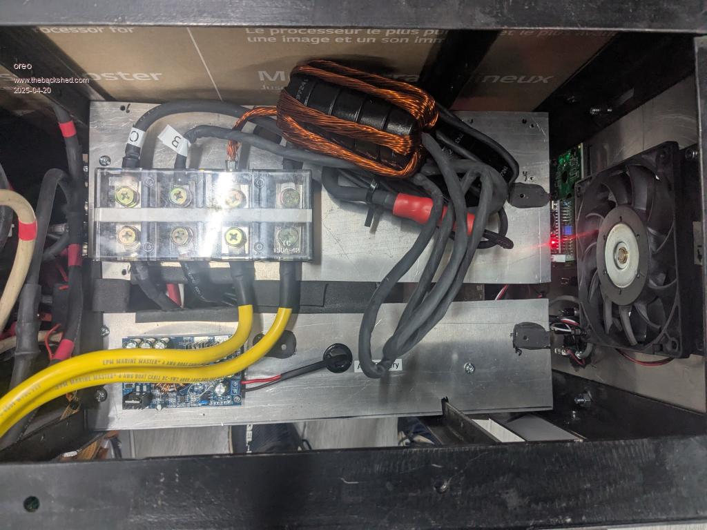 So standby is sitting at 17.5w, which is still reasonable. A few things to sort out. 1. get current measurement working. Now I have split phase which represents a bit of a problem, so I am re-using the current sensors I already have installed. I am just adding the output of the 2 sensors, which means 1 phase could be hogging most of the current, and no-one would be the wiser. Fortunately, the transformers I have are overbuilt on the 120/240v winding. So I have a bit of a safety margin built in. I only want to employ the overcurrent protection, I don't really care how accurate the display is. 2. With the side cover open, the unit is easily tipped, as evidenced by it going over while I was working on it. I need to get the second transformer wound and in their for additional ballast. 3. The duty cycle seems to be indicating that I need a few less primary windings. I will do further testing to see if this needs to be done. 4. At idle, the noise coming from the transformer can either be nearly dead quiet, or a buzz which is louder that one would expect. I recall reading something about this somewhere on the website, so I will need to do a bit more reading. 5. Need to figure out what I am doing on the series chokes. I did build up a gapped core, which I need to test to hear how much noise it makes. Edited 2025-04-20 12:47 by oreo Greg |
||||
| KeepIS Guru Joined: 13/10/2014 Location: AustraliaPosts: 2197 |
Great to see it going  The only time the Toriods make a slightly muted buzz is with a Hairdryer with a Diode in series with the AC for Low power, otherwise it's silent, with a single Toriod, the buzz from that crap load was a lot louder. The buzz at idle, I've heard a slight buzz "very occasionally" on my last single toroid build, but not on the Dual, wiseguy was chasing that on his, he may have more info, but the correct chokes made a big difference to the Last build, obvious it's why I don't hear it an more. With the Duty Cycle, I would not necessarily go by my winding ratio, a while back someone suggested around 82% at Idle with a normal winding ratio Toriod, I don't remember who it was. BTW What does the current indicate when you remove the current sense from the Controller . Edited 2025-04-20 13:40 by KeepIS NANO:Inverter V 8.2ks - Linux AvrDude GUI script V4.1 |
||||
| oreo Senior Member Joined: 11/12/2020 Location: CanadaPosts: 133 |
So I got #1 looked after. There was a bad trace related to a slightly lifted pad between between R5 and C20. Not sure of the cause. Anyway with that jumpered, the current trip is working well now. I tested inrush with my 1.2hp grinder and power hungry drill press and had no start up issues (40 amps @ 120v). Running at 2.4kw for 20 minutes resulted in 21C heatsink and 26C toroid. Next step will be to connect it through the main panel. I am very happy with the results so far. Thanks for the input KeepIS. I hear the buzz more often than not, but at times I can hear the noise ramping up (over a 6-10second period) and then later ramping down. Not a big deal as in reality the inverter is never idling and loads like the fridge, which there is always one running, produce a similar sound on my previous inverter. FWIW, I am currently using a 5 stack of MS184040-2 sendust cores with 9 turns for each inductor, and am using an inductor on both transformer legs. This results in a maximum inductance of 36uH per leg (at 0Amps). From reading this forum, I believe that I should be using a higher inductance due to my higher voltage. So 40uH x 72/48v = 60uH. I am a little over that and will experiment by removing 1 turn which should get me to 60uH exactly. I will report my findings. My thinking on the duty cycle is that when my supply voltage gets close to it's minimum, then I believe the inverter will not support 6kw without a loss in voltage regulation. More testing needs to be done to confirm if this is the case though. On another note, I presume I should be setting the current limit to support a total of 6kw output on 240v? Greg |
||||
| The Back Shed's forum code is written, and hosted, in Australia. | © JAQ Software 2026 |
