
|
|
Forum Index : Microcontroller and PC projects : PicoGAME HDMI - a natural progression
| Author | Message | ||||
| stanleyella Guru Joined: 25/06/2022 Location: United KingdomPosts: 2807 |
but it's all for charity on 2350 hdmi cpu speed set. 2350 vga higher not tried 2040 which runs 40000 or summat. swapped 2040 to 2350 to test. does 2040 run hdmi? is 2350 going to replace it? who's got one? who uses hdmi? who uses usb? |
||||
| phil99 Guru Joined: 11/02/2018 Location: AustraliaPosts: 3293 |
No, RP2350 has internal hardware for it. Not me, plenty of VGA and PS/2 stuff. Not into retro computing and games are best played on a PC, though I see the challenge of writing them could be interesting. PicoMite 1 is a powerful, easy to program and cheap controller and sensor data processor / logger. Also good for home brew instruments such as Volhout's logic analyser. |
||||
| Mixtel90 Guru Joined: 05/10/2019 Location: United KingdomPosts: 8911 |
I like both modules. In some ways the original Pico is a better choice, I think, but time move on and the 2350 has an amazing amount of stuff that is still virtually untouched. We get a bit worked up about its problems, but they are minor really. The Olimex board is good and works well. I'm not denying that. It has a very low WAF (Wife Acceptance Factor) though because to some misguided people it looks naff. My designs look pretty and unobtrusive if you keep the lid on them. :) You only get moans about the wires. This design is also intended to look a little less naff even without the case. :) I've no problems with the HDMI side of things and I know I can get away with odd trace lengths, plug in modules etc. However, in this particular case, one of the things I really want to try is optimizing the HDMI output. I don't want to degrade it. I tried having a VGA module that plugs in over the top of the HDMI socket then closing a solder blob link on two HDMI pins. That was on Alpha, but I thought it was messy. It was a way to rescue the board if I found that I couldn't solder the HDMI socket. It would almost certainly have worked but it's not plug & play as you have an inaccessible solder blob link once it's cased up. Beta and Gamma can be built as either VGA or HDMI as they use the same board area for the socket. It's a one-time-only decision though. PicoTower will have both sockets and you can switch between them. I'm assuming, at this stage, that it will work. Mick Zilog Inside! nascom.info for Nascom & Gemini Preliminary MMBasic docs & my PCB designs |
||||
| javavi Guru Joined: 01/10/2023 Location: UkrainePosts: 562 |
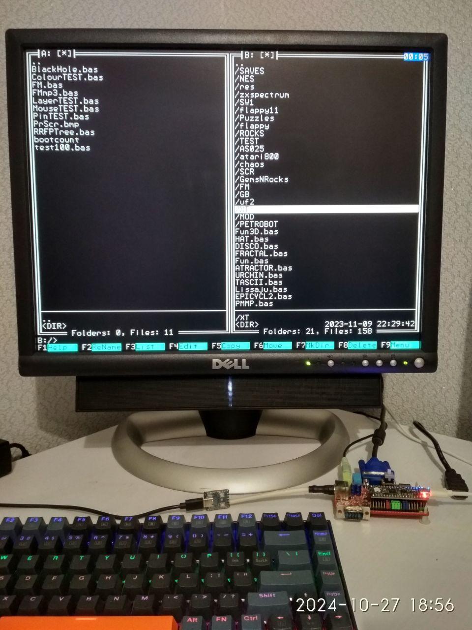 Here in Ukraine we have a lot of second-hand computers from Europe. For example, I bought a Dell 2001FP monitor with VGA, DVI, C-Video inputs and a USB Hub for 10 US dollars for my PicoMite lessons. Yes, I like your PicoTower design, but the only hardware available to me so far is the Murmulator and Pico2 for it. There in the photo, that gray button on top, is the VGA222/VGA121 video circuit switch. Best regards, javavi. Edited 2024-11-14 02:58 by javavi |
||||
| stanleyella Guru Joined: 25/06/2022 Location: United KingdomPosts: 2807 |
Here in Ukraine sh*t, why did I not see this!!?? |
||||
| javavi Guru Joined: 01/10/2023 Location: UkrainePosts: 562 |
I checked the operation of the latest PicoMite HDMI firmware on the Murmulator2 board with a parallel-connected VGA monitor connector. 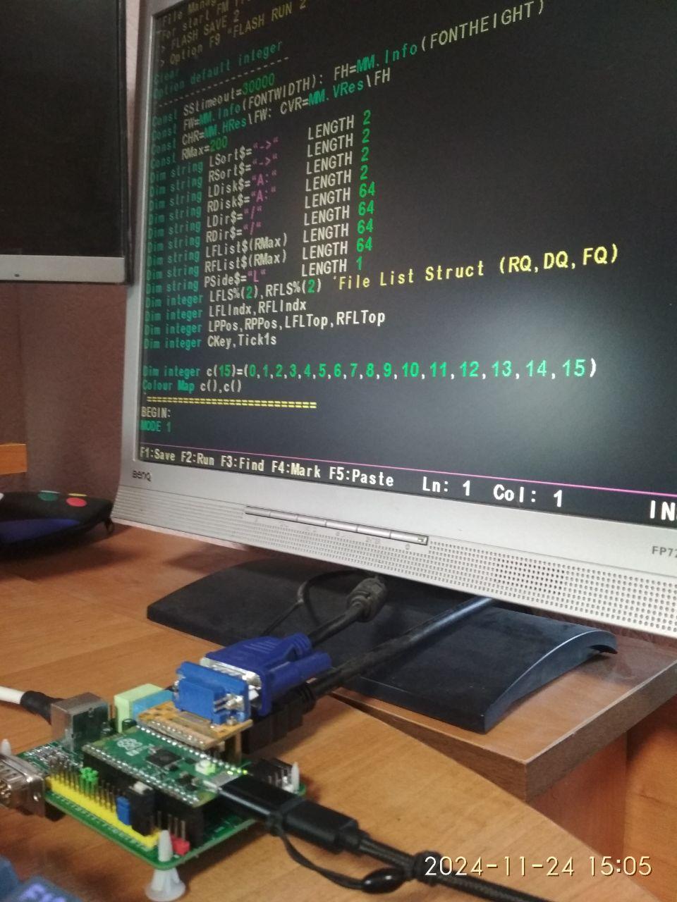 Despite the crooked layout of the HDMI video pins of the HSTX Murmulator2 board and the parallel-connected VGA interface, it works perfectly at a high HDMI resolution of 1024x768 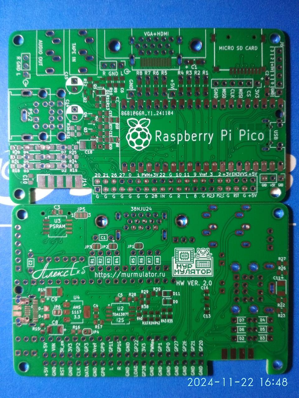 |
||||
| Mixtel90 Guru Joined: 05/10/2019 Location: United KingdomPosts: 8911 |
That's good news for PicoTower, Javavi. :) It doesn't change PicoGAME HDMI though as there simply isn't room for the extra bits involved. There would be no support for the HDMI connector as its fixing holes go nicely through the USB-TTL converter and the HDMI socket - even if I move the Pico further down. It's not going to happen on this one. Mick Zilog Inside! nascom.info for Nascom & Gemini Preliminary MMBasic docs & my PCB designs |
||||
| stanleyella Guru Joined: 25/06/2022 Location: United KingdomPosts: 2807 |
pretty far out. I use vga usb OR hdmi usb boards. not thought of one board with vga/hdmi but then why? thinking adding vga to breadboard dvi is not just change firmware, is it? looking at published designs. one "super" board with hdmi,vga and ili glcd, no that to much but ili as touch mouse maybe, no, use mouse. just thoughts as working on hdmi usb to soldered. or as Chinese sellers say welded. I use a mig for vero... not :) Edited 2024-11-25 09:55 by stanleyella |
||||
| Mixtel90 Guru Joined: 05/10/2019 Location: United KingdomPosts: 8911 |
PicoGAME HDMI Construction pack now available. :) PicoGAME HDMI Construction Pack.zip Mick Zilog Inside! nascom.info for Nascom & Gemini Preliminary MMBasic docs & my PCB designs |
||||
| Volhout Guru Joined: 05/03/2018 Location: NetherlandsPosts: 5934 |
Hi Mick, Manually checked the gerbers, In several locations there are flimsy ground fill lines (floating) between traces. You are using via's in SMT pads. Unless you use filled via's the solder paste will sip through the via, leaving an unsure solder connection. I still have to find how PCB2 puzzle fits together... Volhout Edited 2024-12-11 02:04 by Volhout PicomiteVGA PETSCII ROBOTS |
||||
| Mixtel90 Guru Joined: 05/10/2019 Location: United KingdomPosts: 8911 |
I've not had problems with vias through SMT pads yet, but then again I've only ever hand soldered them. Whether they would be ok if commercially soldered I've no idea! I don't generally design boards for that. PCB2 shows the rear panel upside down and the front panel the right way up. There is a daughter board that mounts on two hex pillars over the D connectors. The full size SD card socket is on top of it and pads for the LED underneath it (it's a normal LED, but surface mounted). There is a very skinny board in the middle with just a Reset button on it. That is mounted inside the top of the case and a flying lead from pads by the button to a connector at the RH side of the main board. The LH end of that pcb is over the USB sockets so will probably need a countersunk screw. Then the two little WII socket adapters complete the collection. Mick Zilog Inside! nascom.info for Nascom & Gemini Preliminary MMBasic docs & my PCB designs |
||||
| Volhout Guru Joined: 05/03/2018 Location: NetherlandsPosts: 5934 |
I ordered the set Let's see what they make of it. Should be able to make it work.Tomorrow I'll look into the parts I need. Volhout PicomiteVGA PETSCII ROBOTS |
||||
| Mixtel90 Guru Joined: 05/10/2019 Location: United KingdomPosts: 8911 |
Welcome to the land of "Mick's Guinea Pigs". :) Thank you for taking the risk. :) Mick Zilog Inside! nascom.info for Nascom & Gemini Preliminary MMBasic docs & my PCB designs |
||||
| Volhout Guru Joined: 05/03/2018 Location: NetherlandsPosts: 5934 |
Haha, I already was Mick. I am a frequent user of the PicoGameVGA revision 1.4. The blue board. Recently build into my ‘rig’. When the boards work, I plan to build 2 for myself, so I have 3 spare. Will send one to you too. Volhout Edited 2024-12-11 04:02 by Volhout PicomiteVGA PETSCII ROBOTS |
||||
| Volhout Guru Joined: 05/03/2018 Location: NetherlandsPosts: 5934 |
Hi Mick, Progress is being made. Not all parts are in yet, but we are half way... 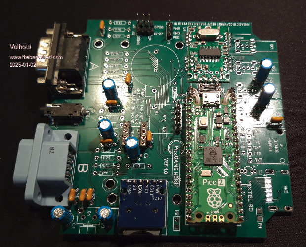 Volhout PicomiteVGA PETSCII ROBOTS |
||||
| Mixtel90 Guru Joined: 05/10/2019 Location: United KingdomPosts: 8911 |
Looking (almost...) good! I'm afraid you have a problem with the USB hub. :( It should have the crystal toward the PCB and be on little legs. I'm annoying, I know. It's a technique I wanted to try after having to remove one from an earlier test board when it was soldered hard down on tiny stakes. I figured that if the constructor had to leave a gap then at least they might be able to cut the wires. I might see about getting some 2mm pitch connectors to try. I find the HDMI socket to be by far the most difficult bit to fit. However, by cleaning both pins and board and keeping the amount of solder paste applied to the absolute minimum you get less tendency to form solder bridges in the first place. This is a "good thing" as getting rid of the little sods at that pitch is a pain. Mick Zilog Inside! nascom.info for Nascom & Gemini Preliminary MMBasic docs & my PCB designs |
||||
| Volhout Guru Joined: 05/03/2018 Location: NetherlandsPosts: 5934 |
Hi Mick, Oops, that is unfortunate. I should have read the manual better. The hub is SMT mounted (with proper kapton insulation under it). Will be a bastard to get that off again. And the holes are like 2mm pitch, so can't use pin headers. Need 20 individual wires. .. Have to keep that for next week. When I am back in the office I may find someone with a hot air system that can remove the hub. sh*t... Volhout EDIT: when the hub is mounted so high up, you can never fit the micro USB in the pico2. So you have to take it out of the socket. Why did you add the DIP switch for the USB disconnect (that I jumpered for now). No use, when you take out the pico2. Edited 2025-01-02 08:18 by Volhout PicomiteVGA PETSCII ROBOTS |
||||
| Mixtel90 Guru Joined: 05/10/2019 Location: United KingdomPosts: 8911 |
The socket on the Pico ends up about 12mm up (8.5mm+2.5mm+1mm PCB) using normal headers. You need plug thickness, but you should still get 8mm or so. There's nothing on the bottom of the hub and the highest component is the crystal, so it should take up about 5-6mm upside down. It certainly looked like it would fit when I was messing about. :) From Alpha I discovered that if D+ and D- were connected to the Pico Windows wouldn't recognise it and you couldn't load MMBasic. It was easy to disconnect them just while doing that. I'm trying to make it so that you don't need flying leads to the pico for any of the four signals that I'm using though, - hence the extra pins - and I simply don't like removing the Pico to reload MMBasic. That led to looking at switches rather than the jumpers that fumble-fingered people like me keep dropping. :( I've found 2mm pitch turned pin male & female headers on AE so I'm going to get a few and try mounting one of these hubs as a plug-in module using 5 strips of 4. Mick Zilog Inside! nascom.info for Nascom & Gemini Preliminary MMBasic docs & my PCB designs |
||||
| Volhout Guru Joined: 05/03/2018 Location: NetherlandsPosts: 5934 |
Mick, Pm your address, so I can send you 2 boards. Volhout PicomiteVGA PETSCII ROBOTS |
||||
| Volhout Guru Joined: 05/03/2018 Location: NetherlandsPosts: 5934 |
Mick, The hub desoldering worked, also the HDMI connector was mounted. Waiting for the last parts to arrive, so I can put it together... Volhout PicomiteVGA PETSCII ROBOTS |
||||
| The Back Shed's forum code is written, and hosted, in Australia. | © JAQ Software 2026 |
