Bleep

Guru

Joined: 09/01/2022
Location: United KingdomPosts: 808 |
| Posted: 09:56pm 21 Feb 2025 |
 Copy link to clipboard Copy link to clipboard |
 Print this post |
|
Hi Peter,
I changed the Init Machine line in the above code to
PIO init machine 1,0,f0,p0,e0,,0,1,0,0
put the Set pin back to 5, at the begining and in the PINCTRL.
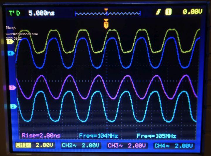
and got the following (image), only showing 2 channels of each, but all 5 SET Pins and 5 Side Set Pins are now working. :-)
I then put another bit in to give:-
PIO init machine 1,0,f0,p0,e0,,0,1,1,0
Which then meant I could remove the line
Set pindirs, &b11111 'set GPIO 0to4 to output
Unfortunately I have a bit of a mix of probes, hence the slightly differing wave shapes. :-(
So my PIO code now is:-
PIO ASSEMBLE 1
.program multi_toggle
.side set 5 '5 side set pins
.line 0 'start line 0
.wrap target
Set pins, &b00000 side &b11111 'set low, side set high
Set pins, &b11111 side &b00000 'set high, side set low
.wrap 'wrap back to wrap_target
.end program list
'configure pio1 StateMachine 0
f0 = 210e6 '100MHz, change this to meet your need
' a b c d e f g 'a,e=side set c,g=OUT b,f=set
p0 = Pio(PINCTRL 5,5,,,GP5,GP0,)
e0 = Pio(EXECCTRL GP0,Pio(.wrap target),Pio(.wrap))
'write the configuration
'PIO INIT MACHINE PIO%,stateMACHINE%,clockspeed[,pinctrl][,execctrl][,shiftctrl][,startinstruction][,sideout][,setout][,outout]
' sideout,setout,& outout can be set to 0 (default) or 1 to specify if pins defined in pinctrl should be INITialised as inputs (0) or outputs (1).
PIO init machine 1,0,f0,p0,e0,,0,1,1,0 'SM0 start at address 0
PIO START 1,0
Thanks for the extra information.
Regards, Kevin. |


