
|
|
Forum Index : Microcontroller and PC projects : Raspberry Pi Monitor doesn't work with PicoMiteHDMI
| Author | Message | ||||
| stanleyella Guru Joined: 25/06/2022 Location: United KingdomPosts: 2807 |
OPTION HDMI PINS clockpositivepin, d0positivepin, d1positivepin, d2positivepin HDMI VERSION ONLY Set the I/O pins used for the HDMI video output. This is only required to suit nonstandard PCB layouts. The positive HDMI signal pins are set according to 'nbr' below. Valid values are 0-7 and the pins must not overlap for each channel. If 'nbr' is an even number the negative output is on physical pin+1, if 'nbr' is odd it will be on physical pin-1. nbr HSTX Nbr Physical Pin 0 HSTX0 GP12 1 HSTX1 GP13 2 HSTX2 GP14 3 HSTX3 GP15 4 HSTX4 GP16 5 HSTX5 GP17 6 HSTX6 GP18 7 HSTX7 GP19 The default is: OPTION HDMI PINS 2, 0, 6, 4 Which means that: CK+ and CK- are allocated to GP14 and GP15 D0+ and D0- are allocated to GP12 and GP13 D1+ and D1- are allocated to GP18 and GP19 D2+ and D2- are allocated to GP16 and GP17 |
||||
| Mixtel90 Guru Joined: 05/10/2019 Location: United KingdomPosts: 8911 |
The only thing I'm aware of that might be strange is that the PicoMite doesn't send the I2C EDID message to request the monitor's resolution. That shouldn't matter as the message originates from the HDMI device, not the display, and the display should either default to a sensible resolution such as 640x480 or use the incoming signal timing to adjust itself. If the timing is way out then it might not display, but the PicoMite can't be that far out as it's fine on many (if not most) displays. A possibility is that the monitor doesn't know the PicoMite is there because the I2C lines aren't pulled up by resistors. That shouldn't happen, but it could, I suppose. I doubt if you could connect them on the Adafruit module unless you are skilled at SMD soldering. They didn't fit the resistor package. (Superfluous info, Stan. The setup works with a different monitor so the HDMI wiring has to be correct.) It would be interesting to test this monitor using the Olimex RP2040 board as that has more signals available on the HDMI connector. . Edited 2025-02-03 03:22 by Mixtel90 Mick Zilog Inside! nascom.info for Nascom & Gemini Preliminary MMBasic docs & my PCB designs |
||||
| javavi Guru Joined: 01/10/2023 Location: UkrainePosts: 562 |
Hi Daniel, What device do you have that you connect to this monitor, can I see the diagram? Maybe I can put together a test firmware for you... |
||||
| stanleyella Guru Joined: 25/06/2022 Location: United KingdomPosts: 2807 |
Mick " (Superfluous info, Stan. The setup works with a different monitor so the HDMI wiring has to be correct.) It would be interesting to test this monitor using the Olimex RP2040 board as that has more signals available on the HDMI connector." I got Olimex RP2040 board with 2350 fitted. it works, as does stripboard But through hdmi breakout board with Inbuilt resistors. why is it a i2c display, do they exist? |
||||
| stanleyella Guru Joined: 25/06/2022 Location: United KingdomPosts: 2807 |
pins in use program For m=0 To 28 :n= MM.Info(pinno "GP"+Str$(m)):print n,"GP"+Str$(m), MM.Info(pin n) :next Sub MM.Startup Local Integer m, n For m=0 To 28 n = MM.Info(pinno "GP"+Str$(m)) If MM.Info(pin n)="OFF" Then SetPin n, DIN, PULLUP Print n,"GP"+Str$(m), MM.Info(pin n) Next End Sub RUN 1 GP0 Boot Reserved : AUDIO L 2 GP1 Boot Reserved : AUDIO R 4 GP2 OFF 5 GP3 OFF 6 GP4 Boot Reserved : SPI SYSTEM MISO 7 GP5 OFF 9 GP6 Boot Reserved : SPI SYSTEM CLK 10 GP7 Boot Reserved : SPI SYSTEM MOSI 11 GP8 Boot Reserved : CONSOLE TX 12 GP9 Boot Reserved : CONSOLE RX 14 GP10 OFF 15 GP11 OFF 16 GP12 Boot Reserved : HDMI 17 GP13 Boot Reserved : HDMI 19 GP14 Boot Reserved : HDMI 20 GP15 Boot Reserved : HDMI 21 GP16 Boot Reserved : HDMI 22 GP17 Boot Reserved : HDMI 24 GP18 Boot Reserved : HDMI 25 GP19 Boot Reserved : HDMI 26 GP20 OFF 27 GP21 OFF 29 GP22 Boot Reserved : SD CS 41 GP23 DOUT 42 GP24 DIN 43 GP25 HEARTBEAT 31 GP26 OFF 32 GP27 OFF 34 GP28 OFF |
||||
| Amnesie Guru Joined: 30/06/2020 Location: GermanyPosts: 757 |
Hi all, thank you very much for you help. I've attached some pictures. @ Mixtel: I did soldered the correct resistor value and it has contact. In fact I've soldered a second one to be sure and measured it. According to the Adafruit schematic it is not neccesary (in this case) to solder the whole resistor network. So is soldered one 10k pullup (see picture) and the original Adafruit PCB layout. This way the 10k pullup goes to pin 19 of HDMI, too. Layout: 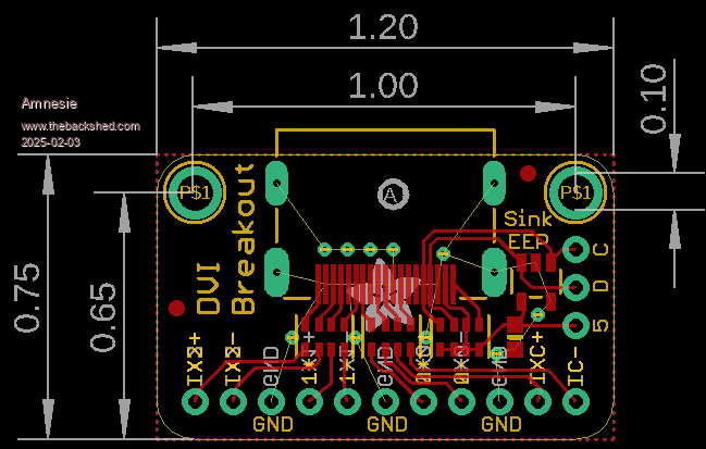 My "hack": 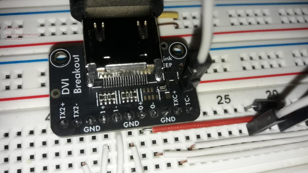 Measurement between GND and Pin 19 HDMI, HDMI-breakout is supplied via Schottky: 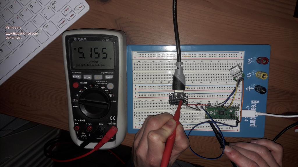 Raspi Monitor not working: 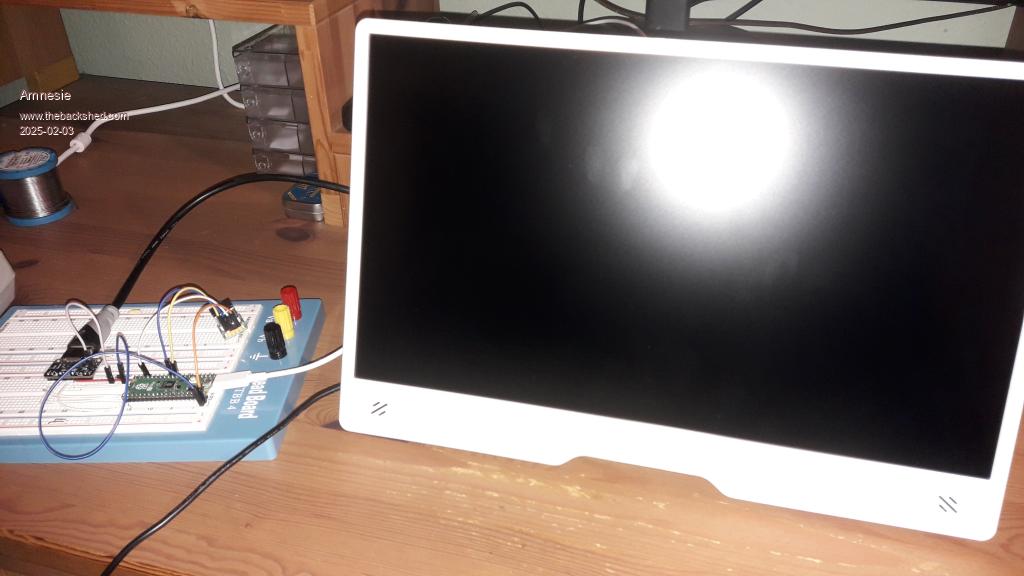 My main work monitor is working: 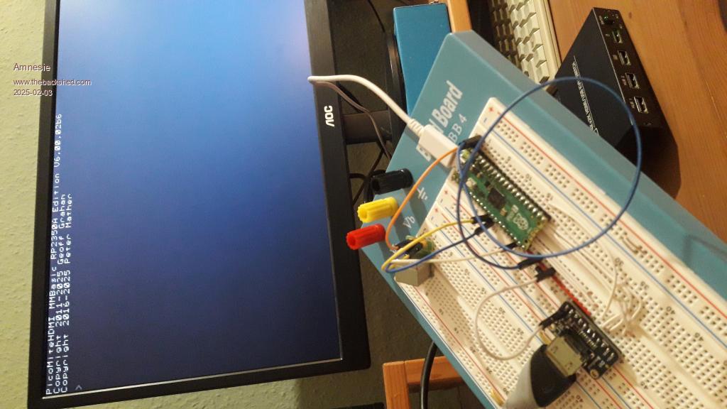 Javi, the schematic is, as said, 100% the default wiring of the manual for the HDMI version, I just connected a PS/2 keyboard for testing... Greetings Daniel Edited 2025-02-03 05:59 by Amnesie |
||||
| Sasquatch Guru Joined: 08/05/2020 Location: United StatesPosts: 385 |
Your solderless breadboard has to much capacitance, I had similar problems until I removed the HDMI breakout from the solderless breadboard and wired it with "flying leads". With the HDMI breakout on the solderless breadboard, it would work with some monitors, not work on others, and be intermittent, limited resolution or other strange behavior on a few. After I got the wiring sorted, it worked on every monitor and TV that I tested. These HDMI signals are not the low frequency signals that we are accustomed to in the micro-controller world. Even at low resolution these are high frequency digital signals. What appears to be a simple HDMI cable is actually a set of impedance-matched transmission lines. Edited 2025-02-03 06:29 by Sasquatch -Carl |
||||
| stanleyella Guru Joined: 25/06/2022 Location: United KingdomPosts: 2807 |
mine started on breadboard and worked and on stripboard ok 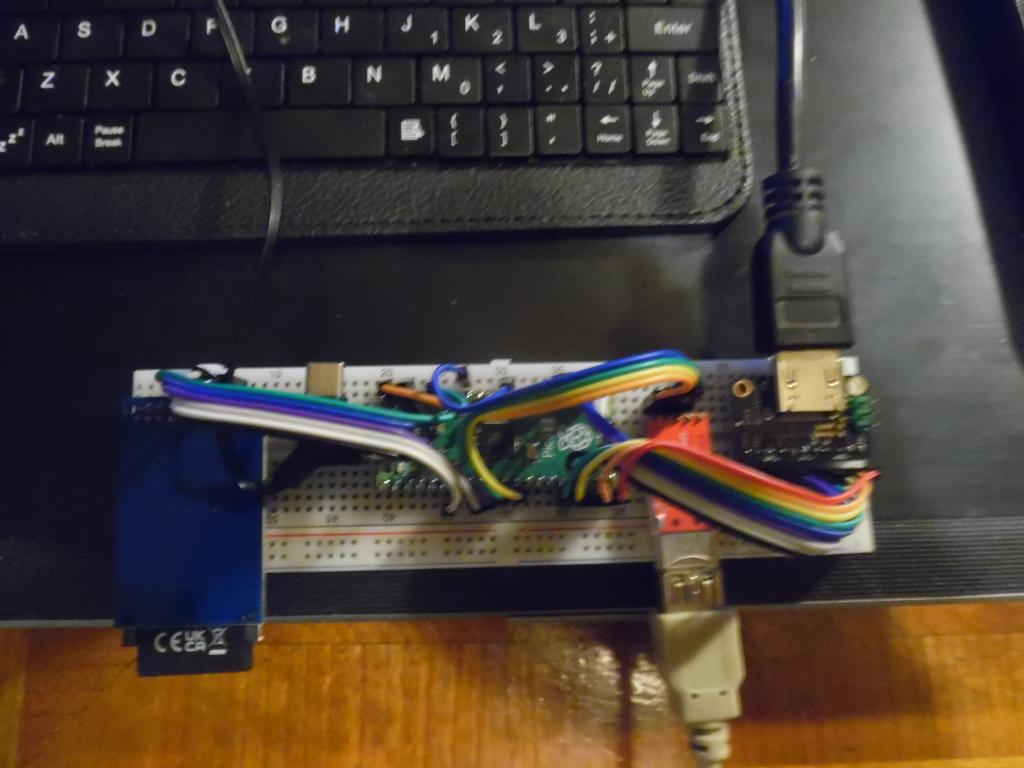 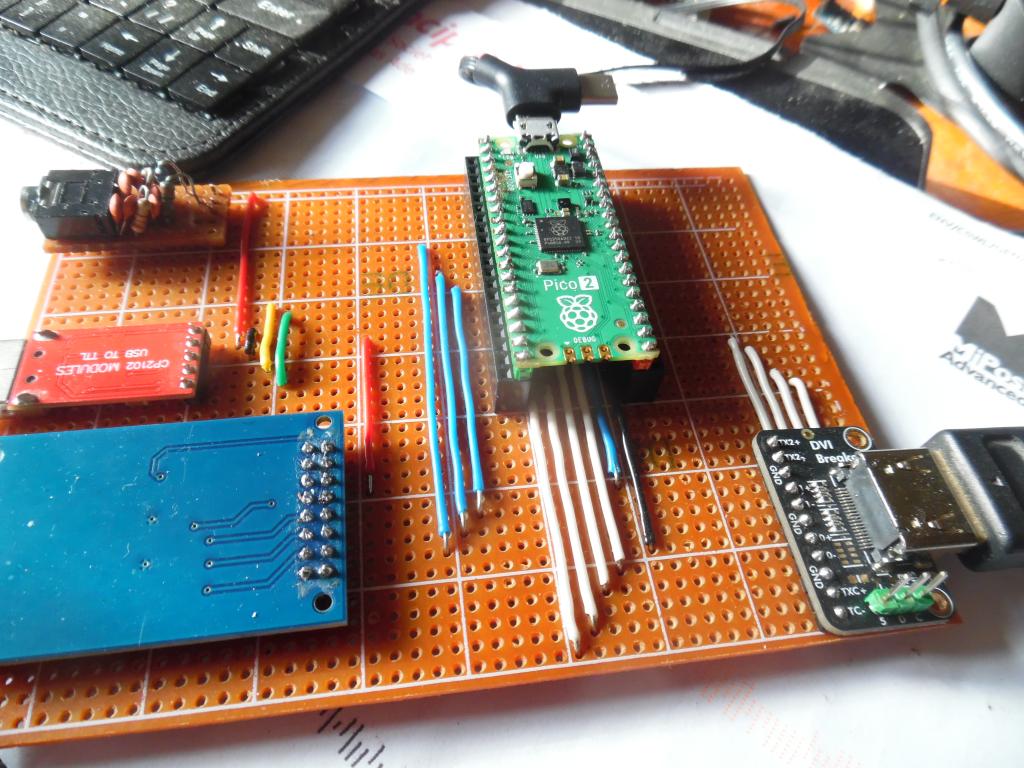 I not got others display probs |
||||
| Sasquatch Guru Joined: 08/05/2020 Location: United StatesPosts: 385 |
See these posts for more information: https://www.thebackshed.com/forum/ViewTopic.php?TID=17229&PID=226429#226429#226429 And the second post with the solution is several posts down the same thread! Edited 2025-02-03 06:42 by Sasquatch -Carl |
||||
| stanleyella Guru Joined: 25/06/2022 Location: United KingdomPosts: 2807 |
no capacitance errors. I found it's the adaptor is ok with bread/strip board. got to be a reason it works on all tvs with hdmi for me. no 5V to hdmi breakout board. |
||||
| stanleyella Guru Joined: 25/06/2022 Location: United KingdomPosts: 2807 |
maybe OPTION HDMI PINS 1, 3, 7, 5 or summat. mine is default so not mentioed in option list but maybe needs setting? |
||||
| Amnesie Guru Joined: 30/06/2020 Location: GermanyPosts: 757 |
I can not verify that. Tried direct soldering with short wire same length. Same problem. Greetings Daniel Edited 2025-02-03 18:55 by Amnesie |
||||
| Amnesie Guru Joined: 30/06/2020 Location: GermanyPosts: 757 |
I now asked for help on the official raspberry pi forum. I am curious if maybe one of the eingineers could figure out what the problem is, since often they are around... This is the Topic: https://forums.raspberrypi.com/viewtopic.php?t=383451 Greetings Daniel |
||||
| javavi Guru Joined: 01/10/2023 Location: UkrainePosts: 562 |
@Amnesie Try to check your monitor with this firmware 640x480 @60Hz HDMI+Audio piconesPlusHDMI.zip Edited 2025-02-04 02:57 by javavi |
||||
| Amnesie Guru Joined: 30/06/2020 Location: GermanyPosts: 757 |
Hi thanks very much for you help. Sadly it doesn't work either. I put this question up on the original Raspberry Pi Forum and one Engineer worte: " Re: Raspberry Pi Official 15,6 Monitor Problems with HDMI Mon Feb 03, 2025 2:15 pm My guess is your are outputting 800x600 which isn't a supported resolution. " But even the 720p doesn't work :D Besides that, I am returning this product (since I bought it a few days ago), I am dissappointed because the approach should be to support even "legacy" resolutions like the cheapest chineese monitor does; either by scaling it to all corners or by shrinking it to a 4:3 ratio. There isn't even an menu... Nahh I am done with this thing :) I Rather switch to other portable monitors which do this "trick" :) Greetings Daniel |
||||
| matherp Guru Joined: 11/12/2012 Location: United KingdomPosts: 11522 |
The responses on your post are typical Raspberry Pi. Everyone is wrong except them and they both know best and are infallible. Same response as everyone gets on the Pico forum when anyone suggests anything is wrong or could be done better. Their engineers seem to be selected for arrogance as well (instead of) of competence. |
||||
| Amnesie Guru Joined: 30/06/2020 Location: GermanyPosts: 757 |
Peter, I already saw your post on the forum there, thanks for this you can explain this better than I ever could. Their response is really sobering. It is what it is, I brought the monitor back to the post office a few minutes ago. This isn't acceptable for me. I mean I really like the monitor for it's size and powerbank / usb powering feature.. But I have always in mind, that even cheaper monitors deliver more for what they are than this thing... I already ordered a new 8" 4:3 ratio monitor from Eyoyo (China) which supports HDMI,AV,VGA etc. I have another "Eyoyo" (but it is only 5") and it works just perfect with HDMI & VGA... something the Pi Monitor obviously can't  Whatever, thanks to all for your help. At least now we know what monitor to avoid. Greetings Daniel |
||||
| stanleyella Guru Joined: 25/06/2022 Location: United KingdomPosts: 2807 |
look up car reversing monitors I got tv android boxes and rasperry pi's to test hdmi. I got no trouble with pico 2 hdmi usb... you are using pico 2. same monitor pico 2 vga usb plugged in. no probs switching via mode/source button. using the same breakout board as you can't see your problem# show option list and pins in use prog results Edited 2025-02-04 08:14 by stanleyella |
||||
| WhiteWizzard Guru Joined: 05/04/2013 Location: United KingdomPosts: 2991 |
Hi Daniel, Just seen your thread about the new RPi HDMI monitor. As soon as these were announced in the UK I went ahead and got one as I new this would be perfect to use with the PicoMite (and the HDMI firmware - in my case, the non USB variant). Ultimately I wanted to use OPTION RESOLUTION 1280 (as this is widescreen format), and also wanted mode 3 to give me more than two colours to play with. Then with I2S sound, it would be a great mobile setup for teaching people to code (and for use in school coding clubs). However, I ran into many issues along the way regarding getting a decent HDMI image. I specifically wanted this RPi monitor, and want round circles (rather than use resolution 640 or 1024 which are 4:3 formats and result in stretched circles). So, I am with you on this one in that using another monitor is not what I’m wanting to do. I can confirm that it is indeed possible to get an image on the monitor but for me it was only partially reliable in 1024. There was noise BUT it did work. 1280 was ver intermittent and variations in DVI socks, length of hdmi lead, and platform also gave random results. Do check if you need to set OPTION HDMI PINS as in my screenshot here in this thread when using an OLIMEX carrier board. For most TVs, the HDMI input will require you to have 5V present on pin 18. Some DVI socks have this set by default, others need a solder-link shorted. I have posted on several other threads about things I tried along the way (ie resistor values, track lengths, other Pico boards, etc) but annoyingly nothing has got me a useable image on any Pico firmware in 1280 resolution on this monitor. I did have success with VGA firmware via a low cost VGA-to-HDMI adaptor BUT there is no widescreen resolution in VGA so hence I am back to seeing stretched circles again! (Not to mention it is mad having to convert vga to hdmi when there is an hdmi firmware available. Sorry if this sounds like a rant, but I have spent many hours trying different things with this monitor. All other HDMI sources I have tried work as they should. @Peter - if I were to get one of these monitors to you, is there anything you’re able to check/tweak/modify in the firmware to get a working image? |
||||
TassyJim Guru Joined: 07/08/2011 Location: AustraliaPosts: 6538 |
@Phil, Have you tried using an active HDMI cable or HDMI splitter as a way to get a buffer amplifier into the path. My gut feeling that better drive will do a lot to help the stability. I don't have any monitor that needs any help so not able to test the assumption here. Jim VK7JH MMedit |
||||
| The Back Shed's forum code is written, and hosted, in Australia. | © JAQ Software 2026 |
