
|
|
Forum Index : Microcontroller and PC projects : 2040 2350 and diy
| Author | Message | ||||
| Mixtel90 Guru Joined: 05/10/2019 Location: United KingdomPosts: 8965 |
Soldering is great! If the fumes bother you get a little soldering fume extractor. You can make one from a PC case fan and some activated charcoal filter like they use in kitchen fans. The fan just sucks the fumes through the filter. Ready built ones usually use a mains fan but I'm sure you could find 12V for a case fan from somewhere. I learned to solder when I was about 10, I think. After a few decades you get used to it. :) Mick Zilog Inside! nascom.info for Nascom & Gemini Preliminary MMBasic docs & my PCB designs |
||||
| stanleyella Guru Joined: 25/06/2022 Location: United KingdomPosts: 2807 |
wanting usb to ttl to be on different pins using > option list PicoMiteHDMI MMBasic USB RP2350A Edition V6.00.02 OPTION SERIAL CONSOLE COM2,GP8,GP9 OPTION FLASH SIZE 4194304 OPTION COLOURCODE ON OPTION KEYBOARD UK OPTION RESOLUTION 640x480 @ 252000KHz OPTION DISPLAY 30, 53 OPTION SDCARD GP22, GP6, GP7, GP4 tried OPTION SERIAL CONSOLE COM2,GP20,GP21 but says invalid option gp22 and gp9 used. just want to wire usb to ttl and sd card reader neater 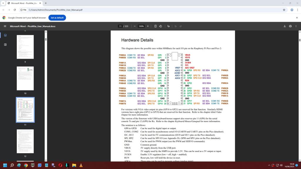 Edited 2025-06-15 06:41 by stanleyella |
||||
| dddns Guru Joined: 20/09/2024 Location: GermanyPosts: 875 |
check syntax |
||||
| stanleyella Guru Joined: 25/06/2022 Location: United KingdomPosts: 2807 |
OPTION SERIAL CONSOLE COM2,GP20,GP21 seems ok syntax using OPTION SERIAL CONSOLE COM2,GP8,GP9 PWM4A COM2 TX I2C SDA SPI2 RX GP8 11 PWM4B COM2 RX I2C SCL GP9 12 27 GP21 I2C SCL COM2 RX PWM2B 26 GP20 SPI RX I2C SDA COM2 TX PWM2A why gp8,gp9 ok but gp20,gp21 not when they both COM2 TX COM2 RX ? stan Edited 2025-06-16 05:36 by stanleyella |
||||
| Mixtel90 Guru Joined: 05/10/2019 Location: United KingdomPosts: 8965 |
By default GP8 and GP9 are reserved. You have to "unlock" them from their job before you can do anything with them. Likewise, if they are set for the serial terminal or PS2 keyboard then you can't put those devices onto GP20 and GP21 until they are freed from GP8 and GP9. Mick Zilog Inside! nascom.info for Nascom & Gemini Preliminary MMBasic docs & my PCB designs |
||||
| phil99 Guru Joined: 11/02/2018 Location: AustraliaPosts: 3322 |
As you say COM2 must be disabled before other pins can be used for COM2 but as this is the USB version he would then have no console to create the new console pins. Does anyone have a clever way out of this? Re-flashing won't help as that is what set GP8 and GP9 in the first place. Edit. Perhaps a future firmware might have OPTION CONSOLE SWITCH PINS ... . Edited 2025-06-16 08:02 by phil99 |
||||
| stanleyella Guru Joined: 25/06/2022 Location: United KingdomPosts: 2807 |
exactly, using usb to ttl for pc input and usb keyboard typing option serial console isn't changing anything. tried option reset. read the manual but not relevant to specific using usb to ttl for version hdmi usb... imho... but I'm thick. I just wanted a flying wire board without any wires from one side of the pico to the other but there's 3.3v from the usb to ttl so that would only be the 5V from usb to ttl to pin 40. still got to do audio on a small vero board. idea was a small total board |
||||
| phil99 Guru Joined: 11/02/2018 Location: AustraliaPosts: 3322 |
Hi Stan, I think I have figured out how to edit an Option .OPT file. Succeeded (on a 2350 VGA Pico) to switch COM2 gp5,gp6 to COM1 gp0,gp1 without disabling the console. After doing this it was just a matter of unplugging the USB/TTL adapter from COM2 gp5,gp6 and plugging it into COM1 gp0,gp1. I try to do the conversion for you for whatever pins you want. Make a .OPT file with:- OPTION DISK SAVE "Stans HDMI USB.opt" This will make the file on A: so copy it to SD card B: COPY "Stans HDMI USB.opt" to "b:Stans HDMI USB.opt" Plug the SD card into your computer and ZIP that file then post it here (file upload - last icon above this window). Edited 2025-06-16 13:31 by phil99 |
||||
| dddns Guru Joined: 20/09/2024 Location: GermanyPosts: 875 |
Manual: OPTION SERIAL CONSOLE uartapin, uartbpin [,B] GP8,GP9 is default for USB versions. Sure you can assign them to any other valid free GPs with this command. True is, that GP8,GP9(default serial) have to be assigned to other pins before you can use them for other issues So initial setup would be: flash USB firmware connect temporarily USB/UART converter to GP8,GP9 change pins to whatever combination connect finally USB/UART converter to new assigned pins. But with every firmware change which probably resets all options to default this procedure would have to be done again. So I would try to use the default GP8,GP9 in any circumstance or @Phils solution with .opt Use LIST PINS to have the best overview Here appendix A from Manual which exactly describes your problem: And the following command for the second channel (referred to as COM2): SETPIN rx, tx, COM2 Valid pins are RX: GP5, GP9 or GP21 TX: GP4, GP8 or GP20 So in your case: Option serial console gp21,gp20 for default 115200 Edited 2025-06-16 15:04 by dddns |
||||
| phil99 Guru Joined: 11/02/2018 Location: AustraliaPosts: 3322 |
Stan's problem is the HDMI USB firmware automatically assigns the console to GP8 & GP9 as the USB console is unavailable. The console can't be moved to any other pins until it is removed from GP8 & GP9. If you try to do that there will be no console (USB isn't available) so you must reinstall the firmware and back to the beginning. Editing the .OPT file in a HEX editor allowed me to change the console com port and pin numbers without deleting the console on the VGA version so we will see if it works on the HDMI USB version. If anyone wants to give it a go I used HEXEDIT.exe. For the 2350 VGA this is what you should see. For com1, pin1, pin2 (GP0, GP1) starting at byte address &H80 the hex bytes are 00 00 00 01 01 02 01 00 For com2, pin6, pin7 (GP4, GP5) starting at byte address &H80 the hex bytes are 00 00 00 02 06 07 01 00 Edit. Also tested on 2040 LCD. Works exactly as above. For both USB and com1, pin1, pin2 (GP0, GP1) starting at byte address &H80 the hex bytes are 00 00 00 05 01 02 01 00 For USB only starting at byte address &H80 the hex bytes are 00 00 00 00 00 00 01 00 Edited 2025-06-16 15:58 by phil99 Footnote added 2025-06-16 18:00 by phil99 From these tests it appears that byte &H83 = 01 for COM1, 02 for COM2 05 for COM1+USB and 06 for COM2+USB. byte &H84 = Tx pin number (NOT GP number) byte &H85 = Rx pin number (NOT GP number) |
||||
| dddns Guru Joined: 20/09/2024 Location: GermanyPosts: 875 |
Maybe it's: Option serial console gp20,gp21 for default 115200 Please try for yourself and post the answer please, I've no chance to test now.. @Phil Thanks for that info! |
||||
| phil99 Guru Joined: 11/02/2018 Location: AustraliaPosts: 3322 |
Option serial console gp21,gp20 works, provided Serial Console isn't being used. > option list PicoMite MMBasic RP2040 Edition V6.00.02 OPTION SERIAL CONSOLE COM2,GP20,GP21,BOTH OPTION FLASH SIZE 16777216 OPTION COLOURCODE ON OPTION CPUSPEED (KHz) 200000 > Edit. For this setup the .OPT file at address &H80 is 00 00 00 06 1a 1b 01 00 Edited 2025-06-16 17:40 by phil99 |
||||
| Mixtel90 Guru Joined: 05/10/2019 Location: United KingdomPosts: 8965 |
I've found that it's not generally a good idea to move the console away from GP8/GP9. It always causes hassle, even if it's only for me in attempting to describe to someone how to do it. It's a situation where hardware wins every time. :) Keep it simple. Mick Zilog Inside! nascom.info for Nascom & Gemini Preliminary MMBasic docs & my PCB designs |
||||
| stanleyella Guru Joined: 25/06/2022 Location: United KingdomPosts: 2807 |
Thanks for the replies guys. it's just irritating you can't use pins for anything you want... got the impression you could. aber nein. gp22 -- i2c2 sda one side of board all i2c2 sda other side used. got to keep gp0, gp1 for audio? point-- I always use soldered headers for mounting pico board.... that's 40 pins that could go faulty before I soldered anything but not mentioned  Edited 2025-06-17 02:09 by stanleyella |
||||
| Mixtel90 Guru Joined: 05/10/2019 Location: United KingdomPosts: 8965 |
You can, largely, use any pins for most things. It's just that it's sometimes a bit awkward to move them round. The HSTX pins are in 4 configurable pairs, for example, but the actual pins used have to be GP12 to GP19 as they are set in hardware. Likewise, the ADC pins are fixed because they are connected to an internal multiplexer for the ADC (there is only one). You *can* move the console around, it's just that there's a bit of hassle involved. The pins used for audio will depend on which audio system! For PWM they have to be any A+B pair of PWM pins. Any will do. Mick Zilog Inside! nascom.info for Nascom & Gemini Preliminary MMBasic docs & my PCB designs |
||||
| Bleep Guru Joined: 09/01/2022 Location: United KingdomPosts: 817 |
Im fairly sure you can use SERIAL CONSOLE DISABLE then re-asign it as you want. |
||||
| phil99 Guru Joined: 11/02/2018 Location: AustraliaPosts: 3322 |
I think Stan has tried that, it works on every platform except USB Host versions as there is no USB console to revert to. Stan I can move the serial console to COM2,GP20,GP21 for you as per this post I have tested it on several configurations and am sure it will work for yours. Edit. Make a .OPT file with:- OPTION DISK SAVE "Stans HDMI USB.opt" This will make the file on A: so use MMCC to copy "Stans HDMI USB.opt" to your computer (or copy it to SD card B: with COPY "Stans HDMI USB.opt" to "b:Stans HDMI USB.opt" Then plug the SD card into your computer) and ZIP that file then post it here (file upload - last icon above TBS Post window). I will change the serial console to gp20, gp21 and post it back here as "HDMI USB gp20 21 console.opt". Then unzip and copy to A: followed by:- OPTION DISK LOAD "HDMI USB gp20 21 console.opt" Update. Loaded HDMI USB firmware, changed the serial console to gp20, gp21 and made the .OPT file for you and here it is:- HDMI USB gp20 gp21 console.zip Edit 2 @dddns was right, you have the syntax wrong. Loaded HDMI USB firmware and typed:- option serial console gp21, gp20 And it changed the console to gp21, gp20 instantly with no errors. So that is all you need to do, ie don't include COM2,. > option list PicoMiteHDMI MMBasic USB RP2350A Edition V6.00.02 OPTION SERIAL CONSOLE COM2,GP20,GP21 OPTION FLASH SIZE 4194304 OPTION COLOURCODE ON OPTION KEYBOARD US OPTION RESOLUTION 640x480 @ 252000KHz > Edited 2025-06-17 11:57 by phil99 |
||||
| stanleyella Guru Joined: 25/06/2022 Location: United KingdomPosts: 2807 |
not tried but connect 2 usb to ttl one to gp8,gp9 and the other to gp20,gp21 and then using the standard to change option serial console gp20,gp21 the other usb to ttl will pick it up ??? |
||||
| stanleyella Guru Joined: 25/06/2022 Location: United KingdomPosts: 2807 |
Ta again for some interesting suggestions.. bit over my head but guess others may have considered pins, just cos of convenient layout on strip board. my idea for diy pico is get bread board and packs of molex cables with male to female and female to female, ribbon looks nice. meant for newbies like me I just think of a newbie that wants to try mmbasic on rpi pico and how to wire a pre-soldered board for £2 more. but as said there's always some soldering. Edited 2025-06-18 02:56 by stanleyella |
||||
| Bleep Guru Joined: 09/01/2022 Location: United KingdomPosts: 817 |
It's a USB, use it, plug a USB keyboard in to the USB socket, ie the one on the Pico, then type:- OPTION SERIAL CONSOLE DISABLE then blind type OPTION SERIAL CONSOLE GP20,GP21,BOTH or whatever gp numbers you are using? |
||||
| The Back Shed's forum code is written, and hosted, in Australia. | © JAQ Software 2026 |
