
|
|
Forum Index : Microcontroller and PC projects : Trying to ID a connector....
| Author | Message | ||||
Grogster Admin Group Joined: 31/12/2012 Location: New ZealandPosts: 9975 |
This is my prototype PCB layout:  Still playing with the idea, but.... Very small PCB - 43mm x 40mm. Will easily fit inside the projector. Smoke makes things work. When the smoke gets out, it stops! |
||||
| Mixtel90 Guru Joined: 05/10/2019 Location: United KingdomPosts: 8911 |
It's a bit posh! I'd have dug a scrap of veroboard out. lol Your mosfet should fully saturate with that low a load. RDS(on) will be 0R1 or less so power dissipation will be about 13 milliwatts! Mick Zilog Inside! nascom.info for Nascom & Gemini Preliminary MMBasic docs & my PCB designs |
||||
| Grogster Admin Group Joined: 31/12/2012 Location: New ZealandPosts: 9975 |
OK, so then perhaps I don't need the copper-heatsink on the drain then!  I was just thinking that I normally run the projector for many hours before I shut it off, so more copper-pour as a heatsink was better then none.  Smoke makes things work. When the smoke gets out, it stops! |
||||
| Mixtel90 Guru Joined: 05/10/2019 Location: United KingdomPosts: 8911 |
It's fine - it won't do any harm to have something to hold the tab down. You almost certainly won't need a lot though. Mick Zilog Inside! nascom.info for Nascom & Gemini Preliminary MMBasic docs & my PCB designs |
||||
| Grogster Admin Group Joined: 31/12/2012 Location: New ZealandPosts: 9975 |
New projector has arrived. I will just check it powers up and down fine, then I will add the mod. Smoke makes things work. When the smoke gets out, it stops! |
||||
| Grogster Admin Group Joined: 31/12/2012 Location: New ZealandPosts: 9975 |
All done, installed and most importantly - working great!  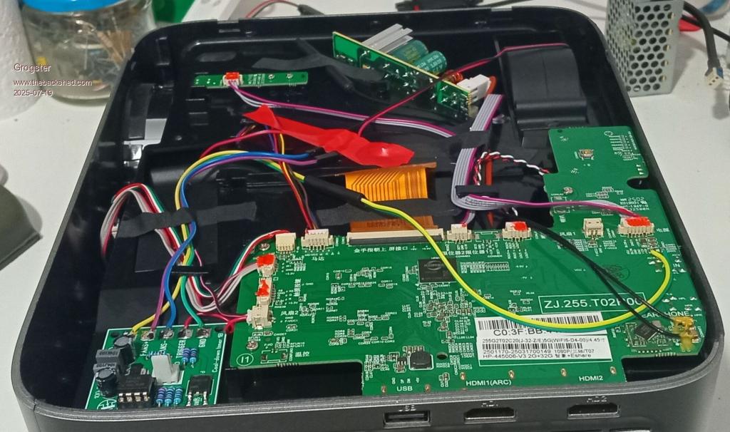 This is version 1B of the cool-down PCB, and I switched the 555 for a PICAXE 08M2. This was because while testing on the bench, the 555 would not reliably keep the fans on. Sometimes it would, other times it would shut them off after about 10 seconds instead of 60 or so. Anyway, it was easier to just plop a PICAXE chip in there, cos then I could easily adjust the cool-down time in code without having to pull parts. Those who look carefully, might note that the design of this projector is good enough, that they have not just buried the LCD in the guts requiring a full disassembly to get to it - note the little plastic clips on the top of the LCD(one on right of image covered with IDC cable and black tape holding wires down) - you can release those, disconnect the FPC cable, and pull the entire LCD up and out of the optical assembly. Very nice design.  About the only thing missing, was a cool-down timer on the mainboard. Perhaps I could suggest it via email with this photo and thread as a bit of evidence? Would they even care though, that's the thing..... Smoke makes things work. When the smoke gets out, it stops! |
||||
Chrisk Senior Member Joined: 21/12/2014 Location: AustraliaPosts: 137 |
Hi Grogster You said you changed to a PICAXE chip for the 555. I too have had problems in some environments. The PICAXE seems a great way to go. Questions 1. What PIC programmer do you use? 2. Can it be programmed for a duration of 3 minutes. 3. Any chance for a copy of the program? Regards Chris K  P.S. As a patriot of this country (not a radical) I love to see the flag and those words "Proudly Made in AUSTRALIA" Thanks Guys |
||||
| Grogster Admin Group Joined: 31/12/2012 Location: New ZealandPosts: 9975 |
Hello. The 8-pin PICAXE is perfect for simple stuff like this, and is small and easy to design into things. 1) I use the AXE-027 USB cable/programmer thing. It is easier and less trouble to use the PICAXE-supported USB cable thing, then trying to use other generic serial programmers. I have had ZERO issues using the PICAXE programming cable thing. 2) It can be programmed for ANY time period you like. That is a simple change in the code, and so you can have cool-down periods from 1 minute to whatever the PICAXE supports. If you want 3 mins, just change 120 to 180 in the timer loop.3) Sure. Here is a copy of the CURRENT code, but you could change this to whatever you like. Would you like the Gerber files for the PCB? #picaxe 08m2 #no_data 'OUTPUT C.0 'C.0 not used, but has to be an output if it is OUTPUT C.1 'C.1 not used OUTPUT C.2 '14N05 MOSFET driver INPUT C.3 'TRIGGER input OUTPUT C.4 'C.4 not used Symbol X=b0 'Variable for the timer loop DO Do:Loop until PinC.3=1 'Wait for projector to power on Do High C.2 'MOSFET "ON" - fans spin up Loop until PinC.3=0 'Keep fans on till TRIGGER input goes low(projector "OFF") For X=1 to 120 '2-min cool-down period Pause 1000 'One second delay Next X Low C.2 'MOSFET "OFF" - fans spin down LOOP Edited 2025-08-12 17:19 by Grogster Smoke makes things work. When the smoke gets out, it stops! |
||||
Quazee137 Guru Joined: 07/08/2016 Location: United StatesPosts: 603 |
Grogster How about C.1 and C.4 as inputs from a dip sw giving you 4 time sets? Quazee137 I used up the PICAXE 08M2s I got from you and was given 50 or so ATTINY85 for a while I'll be using them with the Arduino IDE. |
||||
| Grogster Admin Group Joined: 31/12/2012 Location: New ZealandPosts: 9975 |
Sure. You COULD do that - but I did not do that, as I knew I wanted a 2-minute cool-down, so I just hard-coded it. Smoke makes things work. When the smoke gets out, it stops! |
||||
| lizby Guru Joined: 17/05/2016 Location: United StatesPosts: 3784 |
You can't program a PICAXE from a generic PIC programmer. You must use a chip provided by Revolution Education Getting Started with PICAXE which is pre-programmed with the PICAXE interpreter. You flash your basic program to the PICAXE with the free PICAXE programmer and a special cable. It's a great system and I used it for years, but there has been no new development in about a decade. Still very capable for certain situations. I've just gotten a PCB made by JLCPCB to implement a hardware watchdog using a PICAXE 08M2 or 14M2. @Quazee137 -- I've also purchased some ATTiny85s for this kind of use, but haven't yet gotten around to setting one up. ~ Edited 2025-08-12 23:34 by lizby PicoMite, Armmite F4, SensorKits, MMBasic Hardware, Games, etc. on FOTS |
||||
| Volhout Guru Joined: 05/03/2018 Location: NetherlandsPosts: 5931 |
Hi, The AXE027 programmer used for PICAXE can be replaced by a USB-RS232 cable. I used a CP2102 based interface, and an conversion cable from 9 pin D type to 3.5mm jack. I have no knowledge if FTDI or CH340 based cables also work. Connections: Female D-type 3.5mm jack pin 2 --------------- sleeve pin 3 --------------- ring pin 5 --------------- tip This works fine with 08M2, 14M2, 18M2, 20M2 and also 28pins Volhout P.S. Did you know that Peter was trying to push PICAXE to a higher level, but when he did not get any support ... he turned his focus to MMBasic. And we are glad he did.... On the other hand, it would have been nice to see what he could have accomplished with these simpler chips. Edited 2025-08-12 23:52 by Volhout PicomiteVGA PETSCII ROBOTS |
||||
| lizby Guru Joined: 17/05/2016 Location: United StatesPosts: 3784 |
Didn't you have to program the CP2102 to invert the signals? PICAXE requires the opposite polarity to normal RS232. I use the CH340 (gold) with a PCB which does the inversion. PicoMite, Armmite F4, SensorKits, MMBasic Hardware, Games, etc. on FOTS |
||||
| Mixtel90 Guru Joined: 05/10/2019 Location: United KingdomPosts: 8911 |
It was because of the weird programming and additional cost of PICAXE chips that I first got started with PIC chips, a DIY programmer and GCBASIC. It worked out much cheaper to buy unprogrammed PIC chips (and at that time Microchip would send you a few free samples on request). Additionally, GCBASIC is compiled so it is more powerful and there is more user space. I soon found Chinese clones of the Microchip PICKIT programmer on ebay. :) Mick Zilog Inside! nascom.info for Nascom & Gemini Preliminary MMBasic docs & my PCB designs |
||||
| Volhout Guru Joined: 05/03/2018 Location: NetherlandsPosts: 5931 |
RS232 interface. Not TTL logic UART Volhout PicomiteVGA PETSCII ROBOTS |
||||
| Chrisk Senior Member Joined: 21/12/2014 Location: AustraliaPosts: 137 |
Wow I didn't expect this to grow into such a long discussion. All I want to do is control an exhaust fan for 3 min duration. I thought Grogster's idea of a PIC was a good one and so simple.Ha ha. Not being experienced with PICs I thought a CHEAP PICAXE programmer off ebay would do the trick. That AXE-027 USB cable/programmer is not cheap for a one-off job, and then there are all the other issues discussed by the members. Volhout mentioned a CP2102. How difficult would it be to use this device. https://www.ebay.com.au/itm/304199026251?chn=ps&_ul=AU&_trkparms=ispr%3D1&amdata=enc%3A131oX5IZMS0u7k8uK3K2rFw19&norover=1&mkevt=1&mkrid=705-173151-935305-0&mkcid=2&mkscid=101&itemid=304199026251&targetid=2367800370202&device=c&mktype=pla&googleloc=9071150&poi=&campaignid=21776442415&mkgroupid=173963205248&rlsatarget=pla-2367800370202&abcId=10047386&merchantid=116259179&gad_source=1&gad_campaignid=21776442415&gbraid=0AAAAAD97CxR3XO2BINxUPpD8Eql6wDR1Q&gclid=Cj0KCQjwzOvEBhDVARIsADHfJJSfeduZ78HAWculFQdIlhxD0QiJvg5mf9F3XTFoJjopOtNUle4Q-okaAkbJEALw_wcB If this cannot be used as a simple method of programming I think I will have to look at another way of controlling this fan. Thanks guys for your input. Chrisk |
||||
| phil99 Guru Joined: 11/02/2018 Location: AustraliaPosts: 3291 |
All the PICAXE cable does is provide RS232 signals at TTL voltages. TTL Serial is the same thing inverted. So a pair of any kind of inverter is what you need to adapt any USB / TTL serial converter to the PICAXE. One transistor for each direction will work. For general purpose NPN transistors:- Tx to Base via 10kΩ, Emitter to ground, Collector to Rx and to Vcc via 4.7kΩ. Same in the other direction. Plus ground to ground. If you don't have a USB / TTL serial converter lying around the one on a Arduino Uno or Nano can be used by tying the Reset pin to ground, then connect to the Tx and Rx pins. The Tx and Rx labels on the Arduino are reversed in this mode so Arduino Rx pin to PICAXE Rx via inverter and PICAXE Tx to Arduino Tx pin via inverter. Edited 2025-08-13 12:53 by phil99 |
||||
| Chrisk Senior Member Joined: 21/12/2014 Location: AustraliaPosts: 137 |
Well guys I have bitten the bullet and purchased the PICAXE-supported USB cable after much deliberation and stuffing around. Bought it from AliExpress. Locals were out of stock. I hope it arrives, not like the last thing I bought from them. All up it cost Au$25. Thought about using the USB to USART converter but considering what Volhout and Phil99 said, well that decided it. Thanks to all of you. Chrisk |
||||
| Grogster Admin Group Joined: 31/12/2012 Location: New ZealandPosts: 9975 |
That is a good move. Well, provided the one you got from AE is a half-decent clone of the PICAXE official one. You want the Gerber files for the wee PCB I made? EDIT: AE - I buy HEAPS of stuff from AE, and I have only had one, maybe two issues, and that's over literally HUNDREDS of orders. I actually prefer them to ebay. Edited 2025-08-13 15:51 by Grogster Smoke makes things work. When the smoke gets out, it stops! |
||||
| Volhout Guru Joined: 05/03/2018 Location: NetherlandsPosts: 5931 |
@phil, Remember the original PICAXE design (and their board programmer interfaces) are designed in a time that PC's still had serial ports (but no parallel ports anymore). The 10k/22k resistors are chosen to make the PICAXE chips compatible with +/-9V..12V RS232 interface levels. The 5V output of the chips are correctly for the 1.9V threshold that is typical for RS232 receiver buffers. So no need to limit signals to logic levels. Chrisk: But the choice for a special programming cable is a good one. Otherwise you end up like me: I have a programming adapter cable, but the USB-RS232 cable is re-purposed, so atm I cannot program any PICAXE chips.  Volhout PicomiteVGA PETSCII ROBOTS |
||||
| The Back Shed's forum code is written, and hosted, in Australia. | © JAQ Software 2026 |
