
|
|
Forum Index : Microcontroller and PC projects : PicoBuddy Picomite computer board
| Author | Message | ||||
| DaveC5 Newbie Joined: 24/09/2025 Location: United KingdomPosts: 40 |
@Volhout @javavi Thanks for the observation re: the feedback comp cap, I'll add that. Re: the VGA palette. I like the Windows palette approach suggestions, so the next version will go something like this: 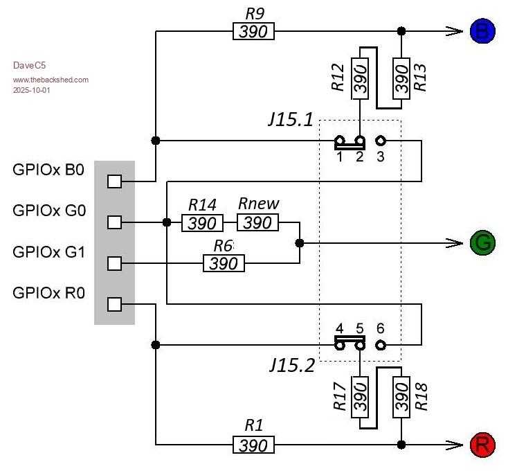 Sticking with the aim of keeping the no. different components to a minimum, this comes within 5% or thereabouts of Volhout's mod using just 390R resistors. It adds an extra one, but has the benefit of using the same value throughout. I can then optimise the BOM by swapping the 3x 470R resistors already on the board (LCD backlight and headphones) to 390R for little practical effect. Changing J15 from a single 2-pin jumper to a 2x3-pin jumper is also no problem and you could wire it to an external switch if you wanted. If anyone is interested I still have a couple of the bare V1.0 boards left over, free to anyone who might be interested in having a tinker. Happy to post them in the UK. Also if anyone is interested in the final version once it's finished I'll share it on PCBWay along with the documentation and the BASIC routines for the LCD etc. Cheers Dave |
||||
| javavi Guru Joined: 01/10/2023 Location: UkrainePosts: 565 |
 |
||||
| Mixtel90 Guru Joined: 05/10/2019 Location: United KingdomPosts: 8935 |
I keep looking for those switches with horizontal mounting but I don't think they are made. :( It means fiddling about with little sub-PCBs so I use these: 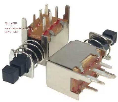 Mick Zilog Inside! nascom.info for Nascom & Gemini Preliminary MMBasic docs & my PCB designs |
||||
| javavi Guru Joined: 01/10/2023 Location: UkrainePosts: 565 |
@Volhout Following your advice, I slightly redesigned the palette switch circuit for the PicoMite VGA. 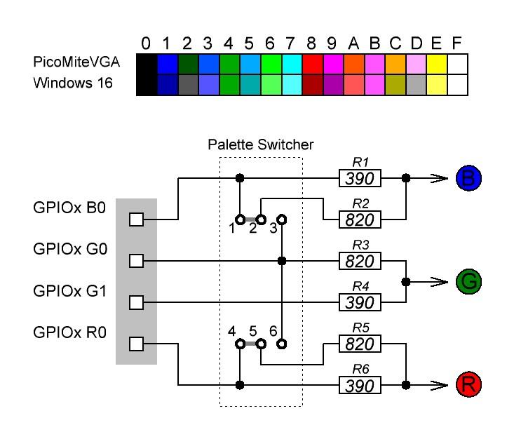 |
||||
| DaveC5 Newbie Joined: 24/09/2025 Location: United KingdomPosts: 40 |
PicoBuddy Computer Documentation.zip The latest version of the PicoBuddy design is finished and uploaded to PCBWay. https://www.pcbway.com/project/shareproject/PicoBuddy_Computer_v1_1_7deba057.html Here are the design and build files for you to use if you fancy having a go a building one. Have fun! Dave Edited 2025-10-27 16:53 by DaveC5 |
||||
| DaveC5 Newbie Joined: 24/09/2025 Location: United KingdomPosts: 40 |
The updated design features the standard or WinVGA palettes suggested in the comments above. I've also tidied up the legends for some of the connectors and also standardised the pin assignments (e.g. Pin 1 is always 0V). The ZIP files contains BOMs, assembly and configuration instructions, mechanical and assembly drawings and some simple code samples. The BOM from Digikey should come in at under 30 GBP at the moment, with everything fitted onboard. BR Dave |
||||
| Volhout Guru Joined: 05/03/2018 Location: NetherlandsPosts: 5975 |
Dave, The audio filter main function is to reject the PWM frequency. In PicoMite Peter standardized at 44.1kHz. The component values you used in the audio filter give 44dB rejection (200 times) on the 44kHz frequency. This is good. It leaves 16mVpp 44kHz ripple at the outputs. But by changing the component values in the filter, you can achieve better. Below values give 70dB rejection, and give less roll off at 10kHz. 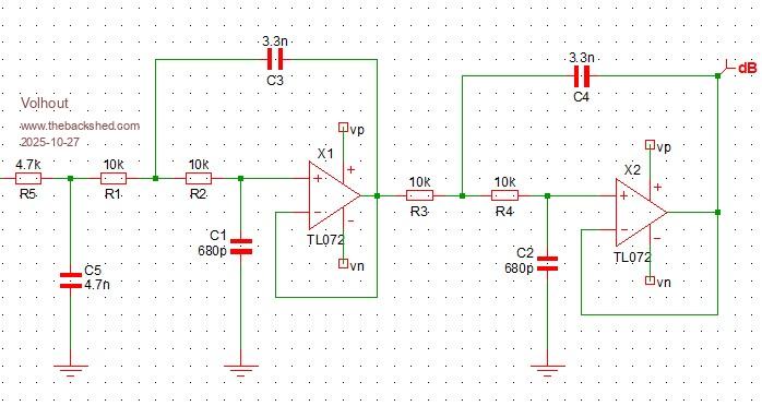 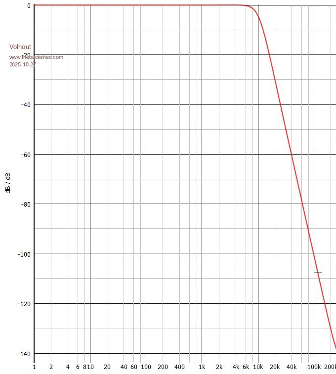 Volhout PicomiteVGA PETSCII ROBOTS |
||||
| DaveC5 Newbie Joined: 24/09/2025 Location: United KingdomPosts: 40 |
Hi Volhout, Nice! I think the noise would be closer to 3-4 mVpp, just because it isn't getting the full 3.3 V swing from the PWM, but yeah, this is a better frequency response. I'd encourage anyone having a go at the PicoBuddy to mod, tweak and optimise as much as they like. It's an open design and there's plenty of scope to fine-tune various parts of the circuit, stepping outside the (self-imposed, admittedly) limited set of components in the BOM. This is a good example; I like the flexibility you get with S&K filters. The documentation also notes that although the analogue input LFP cutoff is around 48 kHz using the BOM parts, swapping the 3.3 kOhm resistors for 10 kOhm from the BOM drops the cutoff to roughly 16 kHz. But of course the builder could use whatever R-C LPF components worked for their application, the buffer amps reduce the need to worry about the input resistor value. Have fun! Dave |
||||
| DaveC5 Newbie Joined: 24/09/2025 Location: United KingdomPosts: 40 |
Here are details of the board assembly for reference  |
||||
| matherp Guru Joined: 11/12/2012 Location: United KingdomPosts: 11603 |
Volhout I'm interested in your active filter. It should be cheaper and better than the passive one with the inductors. I've attached the list of Basic components from JLC. These are the ones that are already loaded in their pick-and-place machines and incur no extra charge. You will see there are no 4.7nF capacitors nor 680pF, There are 330pF which presumably could be paralleled. What is your view on TL072 vs NE5532, they do both One thing I'm struggling with on the Palm Pico is attenuating the signal to match the input of the amplifier which has a gain of 22dB. Could I be really cheeky and ask you to propose a variant that both includes a 10K pot and matches the output to a PAM8406 or PAM8302. DaveC5: I really like your board and apologies for jumping on the thread Basic.zip Edited 2025-10-28 19:14 by matherp |
||||
| Volhout Guru Joined: 05/03/2018 Location: NetherlandsPosts: 5975 |
@Peter, Thanks for the JLC inventory list. Neither TL072 nor NE5532 will do what you want. They need more voltage (+/-5V). But there will be a suitable opamp in JLC inventory. I will tailor the design to meet JLC inventory. I'll PM you when it's done, or post on TBS. Volhout PicomiteVGA PETSCII ROBOTS |
||||
| DaveC5 Newbie Joined: 24/09/2025 Location: United KingdomPosts: 40 |
No problem, this is all good stuff. |
||||
| DaveC5 Newbie Joined: 24/09/2025 Location: United KingdomPosts: 40 |
Hi, I've updated the PicoBuddy (now Pi-PicoBuddy) board with a couple of corrections to the silk-screen and a tweak to the 2N7000 footprint to make it a little easier to solder. V1.2 Updates from V1.1 - JP7 idents corrected - Edge connector pin idents moved so they are not obscured by right-angle headers - Audio filter and analogue input buffer filter bypass points updated - Q1-9 pad spacing increased to simplify soldering The documentation .ZIP file has the Having had a first go on FreeCAD, there are now also .STP files for a two-part case. Images for the port labels are also in the documentation file. 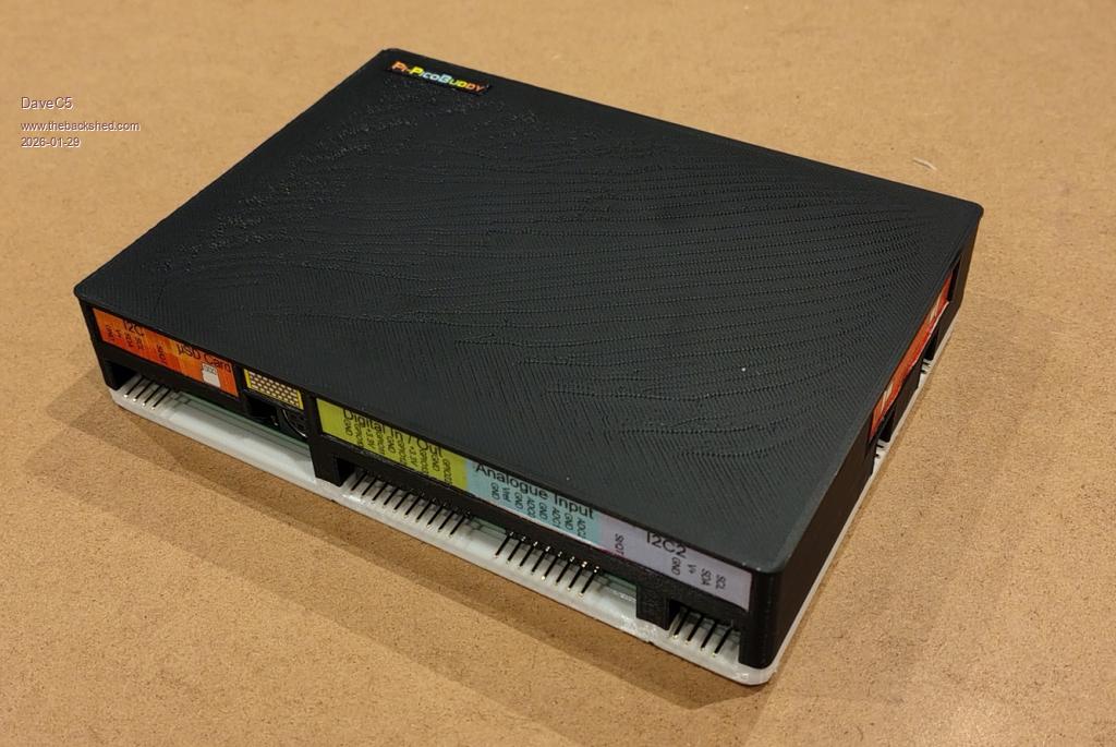 Dave |
||||
| DaveC5 Newbie Joined: 24/09/2025 Location: United KingdomPosts: 40 |
Pi-PicoBuddy Computer Documentation.zip |
||||
| BarryH Regular Member Joined: 05/01/2025 Location: AustraliaPosts: 47 |
Exceptional documentation. A great standard to follow.  BarryH |
||||
| dddns Guru Joined: 20/09/2024 Location: GermanyPosts: 860 |
I think the whole work is exceptional, very nice and accurate! Edited 2026-01-29 19:29 by dddns |
||||
| DaveC5 Newbie Joined: 24/09/2025 Location: United KingdomPosts: 40 |
Thank you! |
||||
| matherp Guru Joined: 11/12/2012 Location: United KingdomPosts: 11603 |
If you post a list of the options needed to configure the board I'll add OPTION RESET PICOBUDDY to the firmware |
||||
| DaveC5 Newbie Joined: 24/09/2025 Location: United KingdomPosts: 40 |
Certainly! There isn't much needed: OPTION KEYBOARD UK (if using a UK keyboard) OPTION SDCARD GP5, GP6, GP7, GP4 OPTION AUDIO GP14, GP15 OPTION SYSTEM I2C GP2, GP3, SLOW The rest of the system is configured using SET commands SET PIN GP0, GP1, I2C to enable the 2nd I2C channel SETPIN 31, AIN to enable AIN_0 SETPIN 32, AIN to enable AIN_1 SETPIN 34, AIN to enable AIN_2 Cheers Dave |
||||
| matherp Guru Joined: 11/12/2012 Location: United KingdomPosts: 11603 |
I assume you are running the VGA version? |
||||
| The Back Shed's forum code is written, and hosted, in Australia. | © JAQ Software 2026 |
