
|
|
Forum Index : Microcontroller and PC projects : RP2040 program for Keypad with more than 4x4 keys.
| Author | Message | ||||
| phil99 Guru Joined: 11/02/2018 Location: AustraliaPosts: 3321 |
There appears to be some interest in a MMBasic driven custom keyboard so here is an expanded version of the Keypad program. It uses one or more 74HC595 serial-to-parallel chips to drive the rows, freeing up Pico pins for a bigger input Port for more columns. 12 columns x 8 rows would give you 96 keys. Still not enough? Add another 74HC595 and go for 16 x 16 = 256 keys! The next firmware release looks like it will have a two pin version of Device Bitstream (perhaps only on the RP2350?). If so the HC595 Sub can be simplified. ' KeyPad_RP2040_74HC595_v03.bas - Program for more than 4x4 Key Pad ' Rows scanned by a 74HC595 serial-to-parallel chip ' rows = number of rows. For more than 8 rows daisychain another 74HC595 chip. ' cols = number of columns ' RowPinGP = row GP pin number for the 74HC595 ' ColPinGP = first of the column GP pin numbers ' Key = number of the key that has been pressed. ' eg. 0 to 63 for 8 columns x 8 rows. 1st row 0 to 7, last row 55 to 63. ' X x Y Keypad with buttons bridging column x to row y Option base 0 Dim integer n, Key=-1, RowPinGP=0, Rows=8, ColPinGP=1, Cols=8 ' Dim KeyMap$(rows * cols - 1)=("Q","W","E","R","T","Y", etc) 'map keys to characters with KeyMap$(Key) if req. Dim integer RowPinNo = MM.Info(pinno "GP"+Str$(RowPinGP)) SetPin RowPinNo, DOUT 'set the output pin to the 74HC595 and set its outputs to 0 HC595 RowPinNo, Rows+7, 0 'Call Sub with DataPin, max. number of Rows, Word to send, 0=all low 'Rows+7 to ensure any unused pins are also set to 0 For n=ColPinGP To ColPinGP+Cols-1 SetPin MM.Info(pinno "GP"+Str$(n)), INTL, Key.Pad, PULLUP 'set the input Port pins and ISR Next Do ' Your main processing loop If Key+1 Then Print "Key";Key, "&H";Hex$(Key,2), Timer-t;"mS" : key=-1 'to retain the value of Key set a flag in the sub and reset it here Loop Sub Key.Pad t=Timer Local integer y, x, x1, n Pause 10 'contact bounce delay, set to minimum value that is reliable For y = 0 To rows 'scan the rows HC595 RowPinNo, Rows, 1<<y Xor (1<<Rows+1)-1 'Call Sub with DataPin, no. of Rows, Row to read, inverted Execute "x1 = (1<<cols)-1 XOR Port(GP"+Str$(ColPinGP)+",cols)" 'read the columns If x1 Then x=Log(x1)/Log(2)+1 If x>cols Or y>rows Then 'check for values out of range and abort this read x=0 :y=0 : Key=-1 HC595 RowPinNo, Rows+7, 0 'prepare for next key input, 0=all low Exit Sub EndIf Key = y * cols + x - 1 'get key no. from row no. and col. no., starting from 0 If x1 Then Exit For Next HC595 RowPinNo, Rows+1, (1 << Rows+1)-1 'all high, block further input to prevent double press Pause 150 'set to minimum value that is reliable, or remove it and/or the HC595 Sub call above HC595 RowPinNo, Rows+7, 0 'prepare for next key input, 0=all low 'Set a flag here if main prog. needs it End Sub Sub HC595 OutPin As integer, R As integer, Dat As integer 'Data output Pin, number of Rows, Word to output Pin(OutPin)=1 'ensure correct polarity for Bitstream Local integer n, el=R*2-1, B(el) For n=0 To el Step 2 'prepare Bitstream array B(n)=3-(Dat>>(el-n)\2 And 1)*2 'low data pulses, 3uS=0 ,1uS=1 B(n+1)=1 '1uS high spaces Next Device BITSTREAM OutPin, R*2, B() 'send it Pin(OutPin)=1 : Pause 0.04 ' >20uS high = latch clock End Sub End ' 74HC595 connections ' 3V3 to pins 16, 10 ' Gnd to pins 8, 13 ' BitStream input to pin 11 (clock) ' pin 11 - 1k8 - pin 14 (data in) - 1n5 - Gnd ' pin 11 - A-diode-K - pin 14 (ser. data in) eg 1N914 or 1N4148 ' pin 11 - 4k7 - pin 12 (latch) - 1n5 - Gnd ' pin 11 - K-diode-A - pin 14 (latch) ' pin 9 (ser. data out) to next 74HC595 (if used) pin 14 (ser. data in), ' parallel pin 11 to pin 11 and pin 12 to pin 12 ' Row output pins:- 15, 1, 2, 3, 4, 5, 6, 7 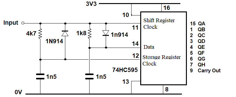 Edited 2026-01-17 15:46 by phil99 |
||||
| Mixtel90 Guru Joined: 05/10/2019 Location: United KingdomPosts: 8965 |
pack of 3 74HC595 is £3.90 + £3.50 delivery from The Pi Hut 1x RP2040-Zero is £1.30 from AliExpress (bundle deal for 3x is £3.90 with free shipping). They now have a RP2350-Zero for £2.90. :) That would make a nice I2C+IRQ X-Y keyboard scanner. 72 keys on 3 GPIO pins. :) Mick Zilog Inside! nascom.info for Nascom & Gemini Preliminary MMBasic docs & my PCB designs |
||||
| phil99 Guru Joined: 11/02/2018 Location: AustraliaPosts: 3321 |
Some years ago I wanted 4 to drive a display. Too expensive in the local shops but just a couple of $ for a tube of 25 from AE, postage included. Now have to find excuses to use them. ;-) |
||||
| phil99 Guru Joined: 11/02/2018 Location: AustraliaPosts: 3321 |
Using the MMBasic Keypad command requires 8 pins for 4 x 4 keys. A 74HC595 and a diode/resistor matrix can read the keypad using just 2 MCU pins. A DOUT scans the keys via Bitstream and a Interrupt Sub reads the pressed key. As with the previous version the rows are driven by idle low outputs. Inverted logic is used to read the columns via diode-resistor logic. Switching the columns is done by more idle low outputs. For more than 16 keys more 74HC595 chips can be daisy-chained. 2 give up to 64 keys and 3 up to 144. Testing was done on a PicoMite MMBasic RP2040 V6.02.00 @ 200MHz and 378MHz. Time taken to read a key (@ 378MHz) and return to the main loop is about 5mS for Key 0, varying up to 10mS for Key 15. It varies because it stops scanning when it finds the key. ' KeyPad_RP2040_74HC595_2_Pin_v01.bas - Program 4x4 Key Pad ' ' Keypad reader using a 74HC595 and 2 MCU I/O pins. ' For more than 8 rows plus columns daisy-chain another 74HC595 chip or two. ' then adjust the Rows and Cols limits for the For / Next loops. ' 1 chip is up to 16 Keys, 2 is up to 64 (8 x 8), 3 is up to 144 (12 x 12) ' keypad does not need to be square. 2 chips = 16 outputs so could do 12 x 4 (12 + 4 = 16) ' Dim Integer Rows = 4, Cols = 4, Key = -1, OutPin=MM.Info(pinno GP0), InPin=MM.Info(pinno GP1) SetPin OutPin,dout : Pin(OutPin)=1 'initialize keypad row output HC595 OutPin,Rows+Cols,0 'set all pins low SetPin InPin,intl,KP_int,pullup 'initialize keypad column input Sub KP_Int Pause 2 'key de-bounce time, adjust to suit your keypad Local integer R, C For R=0 To Rows-1 'Scan the rows (low) one at a time, the rest high HC595 OutPin,Rows+Cols,15-(1<<R) If 1-Pin(InPin) Then Exit For 'exit when the active row is found Next For C=0 To Cols-1 'Scan the columns (low) one at a time, the rest high HC595 1,Rows+Cols, (15-(1<<C))<<4 If 1-Pin(InPin) Then Exit For 'exit when the active column is found Next If Rows-R Then Key = R*Rows+C 'Evaluate the key unless the row count is too high 'Set a flag here if the main loop needs it. HC595 OutPin,Rows+Cols,0 'Prepare for next press, set all pins low End Sub Sub HC595 Out.Pin As integer, RC As integer, Dat As integer 'Data output Pin, number of Rows+Cols, Word to output Pin(Out.Pin)=1 'ensure correct polarity for Bitstream Local integer n, el=RC*2-1, B(el) Array Set 1,B() '1uS low data and 1uS high spaces = all 1s For n=0 To el Step 2 'prepare Bitstream array B(n)=3-(Dat>>(el-n)\2 And 1)*2 'low data pulses, 0 = 3uS, 1 = 1uS Next Device BITSTREAM Out.Pin, el+1, B() 'send it Pin(Out.Pin)=1 : Pause 0.025 ' >20uS high = latch clock End Sub Do If Key+1 Then Print "Key";Key : Key = -1 'If you need to preserve the value of "Key" replace "Key+1" with a flag ' that was set in the ISR and reset the flag instead of "Key = -1" Loop End ' 74HC595 connections ' 3V3 to pins 16, 10 ' Gnd to pins 8, 13 ' BitStream input to pin 11 (clock) ' pin 11 - 1k8 - pin 14 (data in) - 1n5 - Gnd ' pin 11 - A-diode-K - pin 14 (ser. data in) eg 1N914 or 1N4148 ' pin 11 - 4k7 - pin 12 (latch) - 1n5 - Gnd ' pin 11 - K-diode-A - pin 14 (latch) ' pin 9 (ser. data out) to next 74HC595 (if used) pin 14 (ser. data in), ' parallel pin 11 to pin 11 and pin 12 to pin 12 ' 4x4 Row output pins:- 15, 1, 2, 3, ' 4x4 Column output pins:- 4, 5, 6, 7 And the circuit diagram. The Bitstream pin goes to the input and the output goes to the INTL pin. 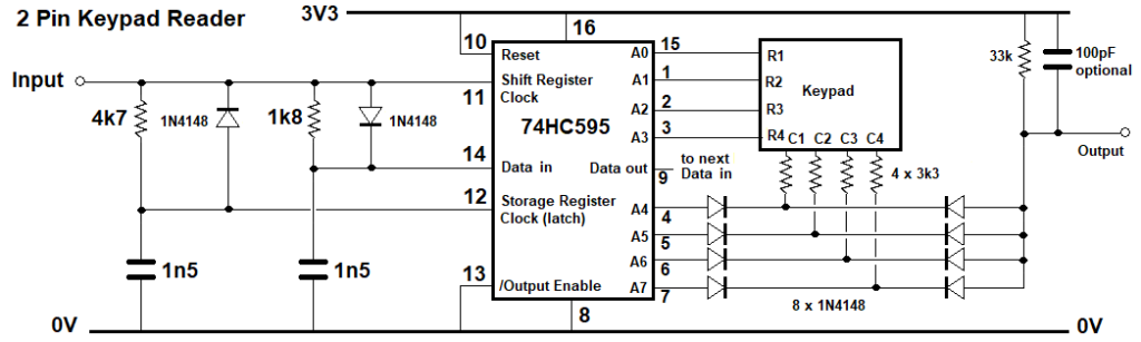 Keypress response times:- Key 0 5.003000006 mS Key 1 4.600000001 mS Key 2 6.101999998 mS Key 3 6.671000004 mS Key 4 4.600999996 mS Key 5 6.107000001 mS Key 6 5.691 mS Key 7 6.275000006 mS Key 8 5.148000002 mS Key 9 6.662 mS Key 10 7.221000001 mS Key 11 7.800999999 mS Key 12 6.663000003 mS Key 13 7.230999999 mS Key 14 6.831 mS Key 15 7.395999998 mS Edited 2026-02-18 16:49 by phil99 Footnote added 2026-02-26 12:34 by phil99 A version for the MicroMite Mk II. The changes account for the lower CPU speed, lower logic threshold voltage and lack of Bitstream command. Tested at 40 and 48MHz. If there are too many button errors replace the 4 output diodes with Schottky types as the forward voltage of regular diodes isn't much less than the logic threshold voltage. Added to that is the voltage drop on the 1k5 resistors, leaving little headroom. ' Keypad reader using a 74HC595 and 2 MCU I/O pins for MicroMite Mk2 ' For MicroMite Mk II v5.05.05, also PicoMite ' Can be expanded to larger keypads with more 74HC595 chips. ' 1 chip is up to 16 Keys, 2 is up to 64, 3 is up to 144 Dim Integer Rows = 4, Cols = 4, Key = -1, OutPin = 4, InPin = 5 Dim map$(15)=("1","2","3","A","4","5","6","B","7","8","9","C","*","0","#","D") SetPin OutPin,dout : Pin(OutPin)=1 'initialize keypad rows HC595 OutPin,Rows+Cols,0 'set all outputs to 0 SetPin InPin,intl,KP_int,pullup 'initialize keypad columns Sub KP_Int SetPin InPin,off :SetPin InPin,Din,pullup 'disable inerrupt while reading t=Timer Pause 2 'key de-bounce time, adjust to suit your keypad Local integer R, C For R=0 To Rows-1 'find the active row HC595 OutPin,Rows+Cols,15-(1<<R) If Pin(InPin)=0 Then Exit For Next For C=0 To Cols-1 'find the active column on the active row HC595 OutPin,Rows+Cols, 255-(1<<C+4)-(1<<R) If Pin(InPin)=0 Then Exit For Next If R<Rows Then Key = R*4+C HC595 OutPin,Rows+Cols,0 'Prepare for next press, set all pins low SetPin InPin,intl,KP_int,pullup 'restore interrupt End Sub ' CLS 0 Do If Key>-1 And Key<Rows*Cols Then Print "Key";Key, map$(key), Timer-t;" mS" Key = -1 EndIf Loop Sub HC595 O.Pin As integer, N.out As integer, Dat As integer ' Data output Pin, number of Rows+Cols, Word to output Pin(O.Pin)=1 'ensure correct polarity for pulses N.out = N.out - 1 'array B() uses Base 0 Local integer n Local float B(N.out) For n=0 To N.out 'prepare data timing array B(n)=(11-(Dat>>(N.out-n) And 1)*6)/1000 'low data pulses, 20uS=0 ,10uS=1 Next For n=0 To N.out :Pulse O.Pin,B(n) :Next 'Send the data (a substitute for Bitstream) Pin(O.Pin)=1 ': Pause 0.02 ' >20uS high = latch clock 'time to get back to main loop is more than this. End Sub End 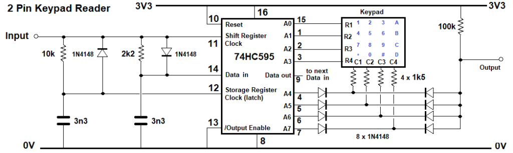 It should also work on the MicroMite Plus and other 'Mites but not tested. Footnote added 2026-02-26 21:34 by phil99 The intention was to have the code cater for more than 4 x 4 keys but one line in the column search loop limits it to 8 outputs. Here is the corrected version, 255 (2^8-1) is replaced by 2^(Rows+Cols)-1. For C=0 To Cols-1 'find the active column on the active row HC595 OutPin,Rows+Cols, 2^(Rows+Cols)-1-(1<<C+4)-(1<<R) If Pin(InPin)=0 Then Exit For Next And here is an example of the output. Key 0 1 11 mS For the 160MHz MicroMite Plus the times could be reduced to something close to the PicoMite by reducing the data and latch time-constants and with corresponding adjustments to the pulse times in the HC595 Sub.Key 1 2 15 mS Key 2 3 18 mS Key 4 4 15 mS Key 5 5 18 mS Key 6 6 22 mS Key 8 7 18 mS Key 9 8 21 mS Key 10 9 25 mS Key 13 0 25 mS Key 12 * 22 mS Key 14 # 28 mS Key 3 A 22 mS Key 7 B 26 mS Key 11 C 28 mS Key 15 D 31 mS For n=0 To N.out 'prepare data timing array B(n)=(11-(Dat>>(N.out-n) And 1)*6)/1000 'low data pulses, 11uS=0 ,5uS=1 (=11-6) Next |
||||
| Volhout Guru Joined: 05/03/2018 Location: NetherlandsPosts: 5994 |
Hi Phil, When you have only 2 pins you can also use a PCF8574, that can be had for few cents on the internet. The PCF8574 is perfect for this in that it has weak pullups, on bi-directional pins. A 4x4 keyboard requires only that chip, nothing else. Not resistors, caps, diodes. But it needs I2C bus. In this test the PCF8574 was connected to system I2C bus on pins GP14 and GP15. This is possible code. Requires between 0.5ms and 1.5ms on a 200MHz RP2040. Dual key presses are reported as key numbers above 32. 'PCF8574 4x4 keyboard 'connect keyboard rows to pins 9,10,11,12, and columns to pin 4,5,6,7 pcf%=&h20 'I2C address when A0/A1/A2 are GND pinrow%=&b00001111 'setup rows and columns, lsb in, msb out 'for decoding Dim pin2num%(15)=(8,8,8,8,8,8,8,3,8,8,8,2,8,1,0,8) Dim rowpat%(3)=(&b01111111,&b10111111,&b11011111,&b11101111) '---------------------------- main program ----------------------- 'init default for rows and columns I2C2 write pcf%,0,1,pinrow% 'main loop Do I2C2 read pcf%,0,1,d% 'read keyboard If d%<>pinrow% Then 'check if key pressed Print whatkey%() 'show the key after scanning End If Pause 100 Loop '------------------------------- subs ----------------------------- 'scan keys Function whatkey%() Local i%,d% For i% = 0 To 3 'scan rows I2C2 write pcf%,0,1,rowpat%(i%) 'push pattern I2C2 read pcf%,0,1,d% 'read response If d%<>rowpat%(i%) Then 'different then key pressed whatkey%=i%+4*pin2num%(d% And 15)'decode I2C2 write pcf%,0,1,pinrow% 'restore default rows Exit Function 'and quit End If Next End Function Tested on V6.02.01b3 on RP2040 In case you have 3 pins available you can also connect the INTn pin on the PCF8574 and do not need to poll at all. For 64 keys (8x8) use 2x PCF8574 on different I2C addresses. Scan time will double. Routing/coding is simplest if you have one PCF8574 do columns, the other Rows. Volhout Edited 2026-02-18 19:46 by Volhout PicomiteVGA PETSCII ROBOTS |
||||
| PhenixRising Guru Joined: 07/11/2023 Location: United KingdomPosts: 2003 |
|
||||
| Volhout Guru Joined: 05/03/2018 Location: NetherlandsPosts: 5994 |
Yeah, I did that one on an Arduino once. Volhout PicomiteVGA PETSCII ROBOTS |
||||
| phil99 Guru Joined: 11/02/2018 Location: AustraliaPosts: 3321 |
The fixed width font of a code box untangles the mess. That looks interesting so will have a go at reading it with MMBasic. It looks like you set the pin as an output to charge the capacitor then switch the pin to input and measure how long it takes to discharge. ┌────────────┐ The keypad that I tested with has an 8-pin header: │ 1 2 3 A │─┳──────┐ 1 - row 2 (4,5,6,B) │ │ 30K │ 2 - row 3 (7,8,9,C) │ 4 5 6 B │─┫ ⏚ 3 - column 1 (1,4,7,*) │ │ 30K 4 - row 4 (*,0,#,D) │ 7 8 9 C │─┫ 5 - column 2 (2,5,8,0) │ │ 30K 6 - column 3 (3,6,9,#) │ * 0 # D │─┫ 7 - column 4 (A,B,C,D) └────────────┘ 30K 8 - row 1 (1,2,3,A) │ ┣┻┻┻────┘ 7.5K ┣─────────────────── I/O pin 1000pF As I mentioned to Mick I have a heap of 74HC595s left over from a project years ago so they are effectively free. They must be good for something! :) Edited 2026-02-19 07:05 by phil99 |
||||
| Volhout Guru Joined: 05/03/2018 Location: NetherlandsPosts: 5994 |
Hi Phil, I used it opposite. Discharge cap, let resistors charge it again. Don’t use a 2350 A2. Mmbasic may be slow to defect some keus. 1000pf/7.5k Volhout Edited 2026-02-19 16:12 by Volhout PicomiteVGA PETSCII ROBOTS |
||||
| dddns Guru Joined: 20/09/2024 Location: GermanyPosts: 874 |
Many thanks for sharing all this useful code and different methods..appreciate it! Another idea is to use an analog input. It might be faster not to wait for the discharge. |
||||
| phil99 Guru Joined: 11/02/2018 Location: AustraliaPosts: 3321 |
I will give that a try too, when I get back to it. As the end of the resistor chain (near the top) points downward I assumed it was going to ground, but it could equally go to Vcc. At first I thought that was how it was meant to work then saw the capacitor, though I guess is could be a noise filter. . Edited 2026-02-19 18:44 by phil99 |
||||
| PhenixRising Guru Joined: 07/11/2023 Location: United KingdomPosts: 2003 |
Take a look at this 3 X 5 decoder |
||||
| bfwolf Senior Member Joined: 03/01/2025 Location: GermanyPosts: 250 |
Ingenious circuit!    How does it work? A square wave oscillator whose frequency is controlled by the keys?  I looked at the example program for the PIC microcontroller, but I didn't really understand it. I looked at the example program for the PIC microcontroller, but I didn't really understand it.  |
||||
| Volhout Guru Joined: 05/03/2018 Location: NetherlandsPosts: 5994 |
All, Frequency changes depending what key pressed. Measure frequency in the arduino/mite. All these single wire keyboards have the same problem. In practise you can make it work for 4, maybe 9 keys. Frequency changes with temperature (logic gates threshold and capacitor drift), so you could get wrong key's identified. More reliable is to feed the resistor divider voltages to an ADC. Resistors typically do not drift much, and ADC's are developed to be accurate. Avoid capacitors and non controlled logic gate thresholds. Another problem with all POLLED systems is that you need to actively check continuously, not to miss a key. The PCF8574 with it's interrupt free's you from that task. But yes... it uses 3 wires (I2C + interrupt). Volhout Edited 2026-02-20 22:45 by Volhout PicomiteVGA PETSCII ROBOTS |
||||
| bfwolf Senior Member Joined: 03/01/2025 Location: GermanyPosts: 250 |
I assume the oscillator also oscillates when no key is pressed? This "fundamental frequency" could be used for regular calibration. This would significantly reduce temperature effects. And if the frequency evaluation is done via a timer input on the microcontroller, and IRQs are used, "software interrupts" could also be triggered when a frequency change is detected. This circuit has another major advantage: only two wires between the keyboard and the microcontroller – and depending on the design, a considerable distance can be bridged. Another advantage: it's difficult to hack – for example, if used to create a combination lock. bfwolf |
||||
| phil99 Guru Joined: 11/02/2018 Location: AustraliaPosts: 3321 |
Had a think about the one pin keypad circuit and came up with this interrupt triggered analogue input version. The 2 33nF capacitors pull the input low enough to trigger the interrupt when any key is pressed. The transistor, pot, diode and 100k form a crude constant current source for the resistive divider chain. This produces linear voltage steps for the keys. The reference voltage is the difference between 5V (VSYS) and 3.3V (Vdd) so ideally requires them to be stable and low noise. The diode provides some temperature compensation for the transistor and ensures the output voltage can't go above Vdd. On the Pico this is just adequate for 16 steps with only occasional errors. For larger keypads a better constant current source will be needed. Also the resistors will need to be precision types. The value of the row resistors should be:- R(row) = R(column) x N columns. For this 4 x 4 version 3.3K is close enough to 820 x 4 but bigger keypads will need to be more accurate. The current source should be adjusted to produce about 3V with the maximum resistance in circuit (bottom right key). Also more 33nF capacitors will need to be connected to the rows to ensure triggering the interrupt. Every third row should be ok. The columns should be ok with just one. 5V________/\/\/\/\___ ____________________________________________AIN GP28 10k pot | | _____________________________ | |_________| | B / E | \ | 1 2 3 A | 3V3____|\|_______|/ PNP | / | | |/| | |\ PN200 | 3k3 \ | | 1N4148 | \ C | / | | | | | |__| 4 5 6 B | | | | \ | | | | | 3k3 / | | | | | \ | | | | | /__| 7 8 9 C | | | | \ | | | | | 3k3 / | | / | | \ | | \ |_________|__| |_/__| * 0 # D | 100k / | | |____________________________| \ 33nF | | | | | |_/\/\/\|_/\/\/\|_/\/\/\| | | 820R 820R 820R | | | _|_ | | 33nF ___ 0V___________|_____________________________|_______________________| 'Interrupt triggered analogue keypad driver using 1 pin. Dim integer key1=-1, key2=-1, n, Rows=4, Cols=4, Key.pin=MM.Info(pinno GP28) Dim Float Vcal=3.09 'calibration voltage - while highest key pressed Dim Kmap$(15)=("1","2","3","A","4","5","6","B","7","8","9","C","*","0","#","D") SetPin Key.pin, intl, Key.int 'set key interrupt Sub Key.int SetPin Key.pin, ain Local key = (Rows * Cols), KeyV If Pin(Key.pin) < 3.2 Then Pause 50 'de-bounce and capacitor charging time If Pin(Key.pin) < 3.2 Then KeyV = Pin(Key.pin) If KeyV >= 3.2 Or KeyV < 0.0001 Then SetPin Key.pin, intl, Key.int 'restore interrupt Exit Sub EndIf key1 = Cint(KeyV * (Rows * Cols -1) / Vcal) Print Format$(KeyV,"% 5.3g"); " V ", 'Comment this out after adjusting voltage ' for highest key (3.0 to 3.1V) then setting the value of Vcal (eg Dim Float Vcal=3.09) EndIf Pause 50 SetPin Key.pin, intl, Key.int 'restore interrupt End Sub Do If key2 <> key1 And Key1 < Rows * Cols Then Print " Key no."; key1, "Key code "; Kmap$(key1) Pause 150 'adjust repeat rate key1 = -1 : key2 = key1 EndIf Loop End ' https://www.thebackshed.com/forum/ViewTopic.php?PID=253854#253854#253854 > RUN 0.0176 V Key no. 0 Key code 1 0.237 V Key no. 1 Key code 2 0.426 V Key no. 2 Key code 3 0.647 V Key no. 3 Key code A 0.863 V Key no. 4 Key code 4 1.08 V Key no. 5 Key code 5 1.27 V Key no. 6 Key code 6 1.48 V Key no. 7 Key code B 1.68 V Key no. 8 Key code 7 1.89 V Key no. 9 Key code 8 2.1 V Key no. 10 Key code 9 2.28 V Key no. 11 Key code C 2.47 V Key no. 12 Key code * 2.71 V Key no. 13 Key code 0 2.87 V Key no. 14 Key code # 3.07 V Key no. 15 Key code D Edited 2026-04-24 22:22 by phil99 |
||||
| robert.rozee Guru Joined: 31/12/2012 Location: New ZealandPosts: 2541 |
there were similar ideas discussed way back in 2014: https://www.thebackshed.com/forum/ViewTopic.php?PID=66729#66729#66729 cheers, rob :-) Edited 2026-04-25 01:08 by robert.rozee |
||||
| phil99 Guru Joined: 11/02/2018 Location: AustraliaPosts: 3321 |
Rob, that is an excellent solution. Especially the self calibration when no key is pressed. Spent some time trying to graft that on to mine but as the extra resistor bridges the rows and columns it defeats the interrupt key detection for most of the keys. Working on an alternative method. |
||||
| robert.rozee Guru Joined: 31/12/2012 Location: New ZealandPosts: 2541 |
you could possibly provide an interrupt signal using a comparator: - connect one input pin of the comparator to the junction of the 470r and 180r resistors. this point should always sit at about 64mV (varying slightly with temperature, but this doesn't matter). - connect a high-value resistive divider between the collector of the PNP transistor and ground. the sum of the divider resistors should be 500k or more. you are wanting to divide the voltage down to around 1/20th, so high value to collector of the PNP transistor, low value to ground. - connect the junction of the comparator to the other input pin of the comparator. - connect the output of the comparator to your interrupt pin. with no button pressed, the voltage at the collector of the PNP transistor will be sitting at a little under 2 volts, so the voltage at the junction of the divider should be at about 100mV. when a key is pressed, this voltage should fall below 64mV. i think! but you'll still need the timer event firing at some slow rate just to do the auto-calibration. cheers, rob :-) Edited 2026-04-25 15:04 by robert.rozee Footnote added 2026-04-25 22:49 by robert.rozee actually, the "high-value resistive divider between the collector of the PNP transistor and ground" does not need to be excessively high-value, as the current it draws flows only through the PNP transistor, bypassing the LM334. so 15k at the top end and 820r at the bottom end would suffice, contributing just another 150uA of current draw to the whole micromite/picomite setup. |
||||
| robert.rozee Guru Joined: 31/12/2012 Location: New ZealandPosts: 2541 |
just had another thought - if you increase the value of the 2k7 resistor that is connected across the "f4" key, you can substantially increase the 'no key pressed' voltage without affecting anything else. with a high enough value, you should be able to push this voltage up to close to 3v3. BUT, if you do this be sure to add a base resistor between the PNP transistor and the LM334, as the LM334 will try to pull 10's of mA to push the voltage across the 470r resistor up to 64mV. with careful selection of the base resistor, you may then be able to hook an interrupt pin directly to the V+ pin of the LM334, no comparator needed; with no key pressed the V+ pin will be LOW, whereas with any key pressed the V+ pin will sit at around 0.6v below 3v3. cheers, rob :-) Edited 2026-04-25 15:19 by robert.rozee |
||||
| The Back Shed's forum code is written, and hosted, in Australia. | © JAQ Software 2026 |
