
|
|
Forum Index : Microcontroller and PC projects : WeAct Pico2350B 48-pin Module
| Author | Message | ||||
| lizby Guru Joined: 17/05/2016 Location: United StatesPosts: 3841 |
Ok, here's my first pass at a PCB for this module: $6.15 for 5 from JLCPCB, including shipping and sales tax, no tariff mentioned.   It may well need a V2 (and V3). Gerbers, zipped EasyEDA, & module files attached. It uses an LCD (ILI9341 or ILI9488), a 5-pin RTC module, an SD module, an ESP8285 module, and optionally a VGA connector module. Provision is made for a 4-channel relay module to be plugged in. I don't know which pin is used to address PSRAM. WeAct-RP2350B-48-pins_V1b.zip ~ Edited 2026-02-09 04:11 by lizby PicoMite, Armmite F4, SensorKits, MMBasic Hardware, Games, etc. on FOTS |
||||
lew247 Guru Joined: 23/12/2015 Location: United KingdomPosts: 1709 |
Can I ask why on the external connector pins you always put 0 and 3.3V next to each other? Not a criticism, just curious because I always thought it best to seperate them, that avoids accidental shorts |
||||
| lizby Guru Joined: 17/05/2016 Location: United StatesPosts: 3841 |
On the 3-pin connectors I put 3V3 in the center to prevent reversing of V+ and 0V. On the connectors with more pins, I find that often what I want to plug in has them next to each other (those 1-, 2-, 4-, 6-, 8-channel relay modules). The RTC module has them on opposite ends, so you really don't want to plug it in backwards with the battery on it. The 37-sensor kits typically have data in the center, so YMMV. PicoMite, Armmite F4, SensorKits, MMBasic Hardware, Games, etc. on FOTS |
||||
| Mixtel90 Guru Joined: 05/10/2019 Location: United KingdomPosts: 8998 |
PSRAM select is on GP0. It is linked via R14 (zero ohm link) so it could probably be changed with careful soldering. There are only 5 possible pins that can be used. I would suggest leaving it as it is. Circuit diagram is Here. Interesting that it uses a crystal rather than a clock module. The regulator is linear. . Edited 2026-02-09 06:50 by Mixtel90 Mick Zilog Inside! nascom.info for Nascom & Gemini Preliminary MMBasic docs & my PCB designs |
||||
| lizby Guru Joined: 17/05/2016 Location: United StatesPosts: 3841 |
Thanks for that. GP0 is the only pin I left unconnected (I think), because I had a vague recollection that it was used for something onboard. Thanks also for the link to the schematic. ~ Edited 2026-02-09 07:19 by lizby PicoMite, Armmite F4, SensorKits, MMBasic Hardware, Games, etc. on FOTS |
||||
| lizby Guru Joined: 17/05/2016 Location: United StatesPosts: 3841 |
I received the 3 WeAct modules. Nothing soldered on yet, but all the OPTION settings I printed on the PCB were accepted without failure (except that the RTC was flagged as not present). I thought the modules included 16MB PSRAM--but there's none--just a set of 8 pads on the back, one of which is connected to GP0. I've ordered some 8MB PSRAM chips--couldn't find 16MB on Aliex or Amazon.  ~ Edited 2026-02-11 03:57 by lizby PicoMite, Armmite F4, SensorKits, MMBasic Hardware, Games, etc. on FOTS |
||||
| ville56 Guru Joined: 08/06/2022 Location: AustriaPosts: 558 |
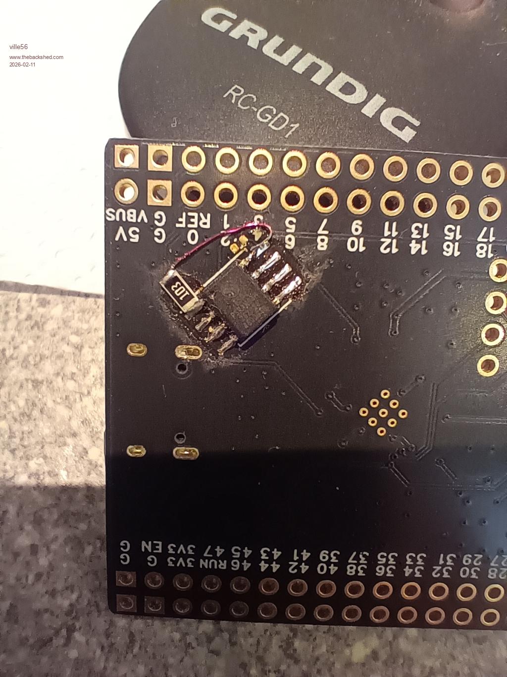
If you add the PSRAM, don't forget to also add the pullup for the CS signal. Otherwise you will get unpredictive behavior. I'll post a picture of my module with the pullup if you like. Gerald 73 de OE1HGA, Gerald |
||||
| lizby Guru Joined: 17/05/2016 Location: United StatesPosts: 3841 |
Ah, I had missed that wrinkle. Please do post a pic. PicoMite, Armmite F4, SensorKits, MMBasic Hardware, Games, etc. on FOTS |
||||
| ville56 Guru Joined: 08/06/2022 Location: AustriaPosts: 558 |
 I did use 10k as pullup, but any other value bt 1k and 10k should do 73 de OE1HGA, Gerald |
||||
| v.lenzer Senior Member Joined: 04/05/2024 Location: GermanyPosts: 131 |
Are those the ESP-PSRAM64H modules in the SOP-8? I'd also like to try the RAM expansion. Best wishes! Joachim |
||||
| Solar Mike Guru Joined: 08/02/2015 Location: New ZealandPosts: 1228 |
LCSC has some PSRAM , can someone confirm if they will work ok. Cheers Mike |
||||
| ville56 Guru Joined: 08/06/2022 Location: AustriaPosts: 558 |
SOP-8 is correct. Gerald 73 de OE1HGA, Gerald |
||||
| ville56 Guru Joined: 08/06/2022 Location: AustriaPosts: 558 |
Organization: 16Mb, 2M x 8bits The one I use has 64 Mbit .... 73 de OE1HGA, Gerald |
||||
| darthvader Regular Member Joined: 31/01/2020 Location: FrancePosts: 100 |
I get the 64mbits ESP-PSRAM64H here : Aliexpress They will be there soon , i hope they are not fake  Theory is when we know everything but nothing work ... Practice is when everything work but no one know why ;) |
||||
| Mixtel90 Guru Joined: 05/10/2019 Location: United KingdomPosts: 8998 |
Whether you need the pullup on PSRAM_CS is questionable, unless you find that it won't work without. It only does anything while the RP2350 is booting. Once that is over the QSPI select pin is probably driven high or low in the usual totem pole mosfet way. You definitely need it if you are going to run with the PSRAM connected and with the CS output pin floating though. Winbond don't actually specify a pullup, they only say that one can be used. Mick Zilog Inside! nascom.info for Nascom & Gemini Preliminary MMBasic docs & my PCB designs |
||||
| ville56 Guru Joined: 08/06/2022 Location: AustriaPosts: 558 |
I own two of this modules with retrofitted PSRAM. From my experiance, for reliable operation, it is absolutely necessary to have the pullups. Reason: after flashing a new firmware the PSRAM pin is usually floating (equal to option psram disable) thus booting up in this virgin state is not reliable if successful at all. Once you get "option psram pin gpxx" to work, I did not see much problems except a few occasional boot failures (hangs). Also if you look at the schematics from WeAct for the modules, they have a pullup provided for CS of the PSRAM. 73 de OE1HGA, Gerald |
||||
| Mixtel90 Guru Joined: 05/10/2019 Location: United KingdomPosts: 8998 |
Maybe Raspberry Pi are keeping quiet and waiting for someone to get the RP2350B working reliably before they commit to designing their own module for it. ;) They got a bit bitten by the Pico W, I think. lol You're right. It's always a good idea to pull CS signals in the "disable" direction so that they have to be deliberately enabled. Mick Zilog Inside! nascom.info for Nascom & Gemini Preliminary MMBasic docs & my PCB designs |
||||
| JohnS Guru Joined: 18/11/2011 Location: United KingdomPosts: 4361 |
Peter's board? John |
||||
| Mixtel90 Guru Joined: 05/10/2019 Location: United KingdomPosts: 8998 |
Perhaps they don't fancy having to trim the voltage on theirs. :) Mick Zilog Inside! nascom.info for Nascom & Gemini Preliminary MMBasic docs & my PCB designs |
||||
| lizby Guru Joined: 17/05/2016 Location: United StatesPosts: 3841 |
Before and after PSRam soldered on: So what is the additional ram useful for? Heap? What else? PicoMite, Armmite F4, SensorKits, MMBasic Hardware, Games, etc. on FOTS |
||||
| The Back Shed's forum code is written, and hosted, in Australia. | © JAQ Software 2026 |
