
|
|
Forum Index : Windmills : Progess photos
| Author | Message | ||||
JimBo911 Senior Member Joined: 26/03/2009 Location: United StatesPosts: 262 |
The minor diameters of the groves I machined in my blade stubs ares approximately .670 thousandth of an inch or 17mm. The minor diameter of the grove machined in the F&P shaft that comes from the factory is approximately .710 thousands of an inch or lets say 20.2mm. I see a difference of 3.2mm. Lots of the mills that use F&P stators and shafts are being used to mount the entire hub and blade assembly not just one blade. The hub and blades on the F&P set up are fixed to the shaft (only) while my blades and hub are bolted to a 10 inch or 250mm cast iron drum. I will have to agree with Gordon the survivability of any mill has to do with the entire assembly ie, tower, tail, balance etc. 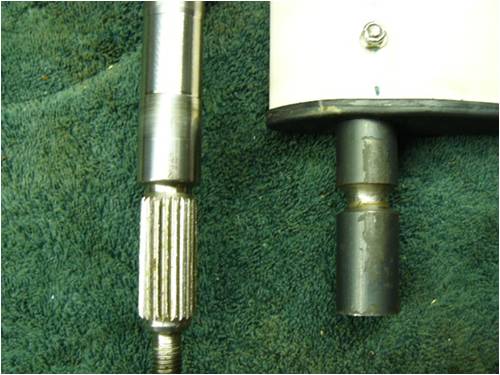
Jim |
||||
montyLalor Newbie Joined: 17/12/2008 Location: AustraliaPosts: 21 |
Okay, but consider this: the F&P shafts are stainless; your blade bar looks to be cold-rolled bright mild. There immediately is a key difference. Also, the hub groove on the F&P shaft is a point of rotational flex that will somewhat dampen the odd loads your mill will encounter, and yes, it will fail one day, but "choice" material selection has helped the OEM shaft to no end. It would have been a design compromise to make it easier to broach the spline at manufacture. Conversely, your blade groove is constrained in predominately one direction, potentially leading to a fracture caused by long-term, semi-uni-directional fatigue. It won't break tomorrow, nor next month. The collision survival prooved this. But mild steel is called mild steel for a reason. Moreover, the 3.2mm (1/8") difference in the grooves you measured may not seem too much, but remember, it's not the groove's sizes you need to looking at and comparing, it's the percentage of bar removed to create the groove, and thus, the percentage of remainder cross-sectional area compared to the shaft's original diameter. Your extended groove length at the smaller diameter when visually compared to the F&P shaft is, in my opinion, the greatest cause for concern, long term. Luke "So are you doin' this project to make us money or cost us money?" she asks again... |
||||
MacGyver Guru Joined: 12/05/2009 Location: United StatesPosts: 1329 |
On home-made blades and fastening them: Having viewed the tensile "parting" specs on T-6 aluminum one thing I can tell you is it actually gets stronger just before it parts. This is why I make all my blades out of solid aluminum. I don't worry about airfoil or drag; I merely let the flat blade bite the wind and that's that. One thing I should mention is; the longest blade I currently manufacture and use is 3 feet long. That makes the total sweep a little over 6 feet (diameter). My "normal" length blade is only 24 to 30 inches. Many years ago, I manufactured a "Clark Y" out of sheet aluminum and was able to twist the thing so the tip ran with almost no pitch, while the root was set at 45 degrees. If anyone is interested in doing it this way, say so and I'll throw up a tutorial. By the way, in those days, I ran 7-foot blades in a Jacobs (three-blade) fashion and each blade weighed in at less than a pound. The root was through-bolted with massive solid-aluminum plates to discourage wandering. I used (and still do) a solid aluminum hub plate and twist the tangs to achieve pitch. There was also an aluminum tube that ran up the center just under the apex of the airfoil to discourage bending when the tail spun the turning blades across their axis of rotation. The tube was pop-riveted to the blade. My thinking is that if the blades are manufactured on the order of a pinwheel (lightweight and balanced), the forces of nature will have to get really out of hand before any trouble arises. My solid-blade design would have to spin faster than any wind will make them go before they even approach parting speed. Oh, by the way, solid aluminum blades make a rather awesome "gong" sound when a bird isn't paying attention! To give equal time, a careless bird can really wreck a hollow Clark Y blade! Another "feature" of a hollow blade is they tend to "pump" a stream of air through the center of the thing and out the tip. This somehow spoils some of the noise in high winds. Nothing difficult is ever easy! Perhaps better stated in the words of Morgan Freeman, "Where there is no struggle, there is no progress!" Copeville, Texas |
||||
| montyLalor Newbie Joined: 17/12/2008 Location: AustraliaPosts: 21 |
This would be work-hardening? Luke "So are you doin' this project to make us money or cost us money?" she asks again... |
||||
| MacGyver Guru Joined: 12/05/2009 Location: United StatesPosts: 1329 |
montyLalor: Here's how the test goes: A piece of T-6 bar stock is clamped between two steel I-beams and the beams are forced apart with a hydraulic ram. A gauge is in place to measure both the increase and the "parting" pressures. As the test proceeds, there comes a point when it looks like the metal will part, but then it gets a second wind and the actual parting pressure has to go WAY up before it does the deed. I suppose this could be a form of 'work-hardening'; I don't know. What I do know is there's no wind I've ever seen that can spin a windmill fast enough to create enough centrifugal force to part the solid T-6. I have designed and built my blades for years based on these findings. As stated, I've also manufactured hollow blades, but they are way more work and you can cut the heck out of your fingers if you're not careful. I've done it and it's like a paper cut; you see blood before it hurts, but then it hurts like hell for a week! Nothing difficult is ever easy! Perhaps better stated in the words of Morgan Freeman, "Where there is no struggle, there is no progress!" Copeville, Texas |
||||
| montyLalor Newbie Joined: 17/12/2008 Location: AustraliaPosts: 21 |
Highschool was a while ago for me now, but I think what you are referring to is a yield test. The tensile strength is overcome upon the first stretching, and then the yield strength is finally overcome upon the material's breakage. The 'second wind' you mentioned is the material work-hardening after tensile strength is overcome, making it stronger, but more brittle. Finally the material's yield strength is much greater than its tensile strength; hence �the parting pressure going WAY up� before it breaks the bar. I welcome any corrections to my material science theories. Luke "So are you doin' this project to make us money or cost us money?" she asks again... |
||||
| JimBo911 Senior Member Joined: 26/03/2009 Location: United StatesPosts: 262 |
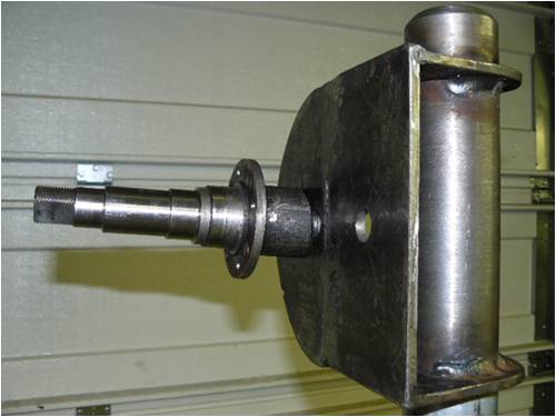
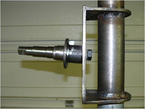
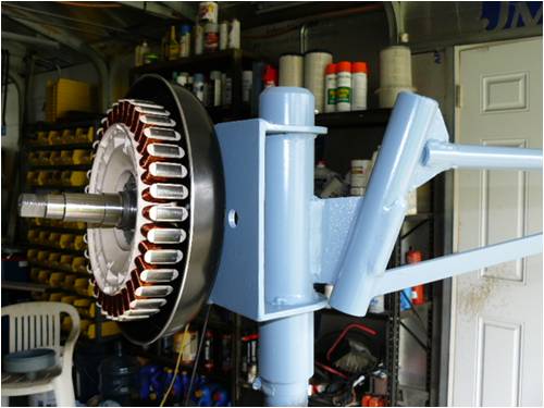
Off set, blade tilt. Ok I think I may have something here. Adjustable off set at 76 mm, 101.5mm and 129mm. Blade tilt at or around 4 degrees. I machined the end of the spindle to get the tilt. Hopefully this may work for me. Comments please. 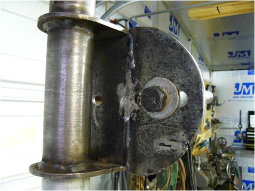
Jim |
||||
| GWatPE Senior Member Joined: 01/09/2006 Location: AustraliaPosts: 2127 |
Hi Jim, It may have been easier to slot the top brace, and reweld with the amount of angle. You will need to stop the stub axle from rotating now. Gordon. become more energy aware |
||||
oztules Guru Joined: 26/07/2007 Location: AustraliaPosts: 1686 |
pin it Village idiot...or... just another hack out of his depth |
||||
| JimBo911 Senior Member Joined: 26/03/2009 Location: United StatesPosts: 262 |
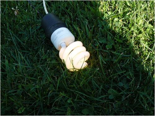
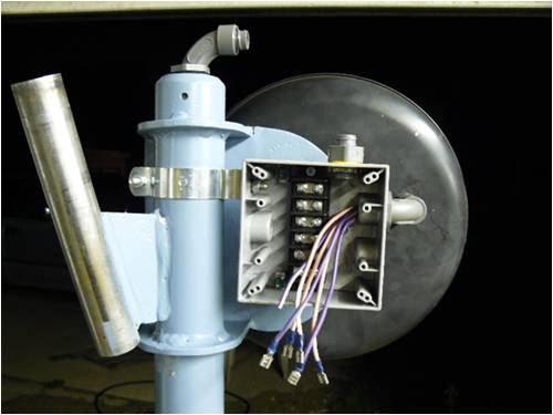
I know it's not the prettiest looken thing but hell who's going to see it close up when she finds her new home LOL. Already started the tail pivot. Woke up last Sunday to the sound of wind rustling the tress around, I couldn't stand it any longer so I set out to make my first electron. Made up a quick tail, installed the stator' called out my women and pulled up a couple of chairs. You should have seen us sitting there waiting for the voltage meter to display some numbers I think the neighbors where thinking (Dam I think those two are losing it). Well we did see voltage and better yet we got to see the CF bulb lite up. May not seem like much to some of you guys but to us it was a special day.  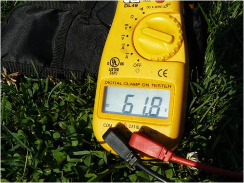
Jim |
||||
| Gizmo Admin Group Joined: 05/06/2004 Location: AustraliaPosts: 5187 |
Well done Jim. 
Glenn The best time to plant a tree was twenty years ago, the second best time is right now. JAQ |
||||
| oztules Guru Joined: 26/07/2007 Location: AustraliaPosts: 1686 |
There is something tragic about sitting there watching the amp gauge (or voltage if no batts hooked up).... waiting for the next gust to see if it can do a bit better than the last.. could do it all day.... small things small minds says the missus .....oztules Village idiot...or... just another hack out of his depth |
||||
| Janne Senior Member Joined: 20/06/2008 Location: FinlandPosts: 121 |
I agree. If you have a TV in your windpowered system, it will be much more fun watching the amp gauge in windy weather than the TV :) If at first you don't succeed, try again. My projects |
||||
| JimBo911 Senior Member Joined: 26/03/2009 Location: United StatesPosts: 262 |
A bread apart that's what we are. I like being the Solar Geek in my neighbor hood. I use to have the BIGGEST mill in Dupage county (Air X lol) until we installed my neighbors Sky Stream ever since then my women say's I've been suffering from Turbine envy. Thanks to all involved. Jim |
||||
| montyLalor Newbie Joined: 17/12/2008 Location: AustraliaPosts: 21 |
Love the G-clamp! Reminds me of an old boss of mine from a few years back. He built a sheet-metal slitting machine about twenty years ago, that, until a couple of years ago, was almost entirely held together with varying sizes of G-clamps. Yes, he's an engineer! Gold! Luke "So are you doin' this project to make us money or cost us money?" she asks again... |
||||
| JimBo911 Senior Member Joined: 26/03/2009 Location: United StatesPosts: 262 |
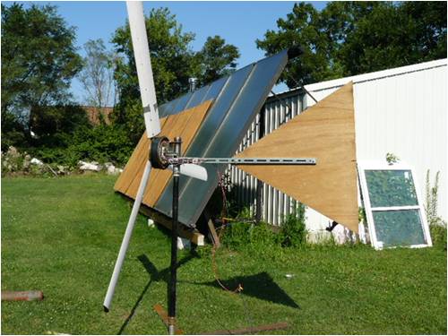
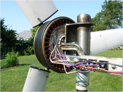
Completed more work on my mill here are the progress photos. My women and I where driving in the car yesterday when all of a sudden she hit the brakes(she was driving) and hung a quick u turn so I asked her what was that all about and she said I JUST FOUND OUR NEW TAIL FIN. I will also install a nose cone when possible. Of course now that I am ready to start producing some juice (wind trials) there's no wind to be found. I had a difficult time figuring out a way of keeping the weather out of the stator but finally went to Wallmart and bought a saut'e pan to use as a backing plate/weather protection it will also provide cooing. 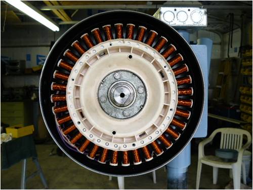
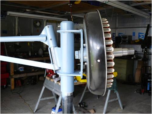
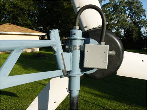
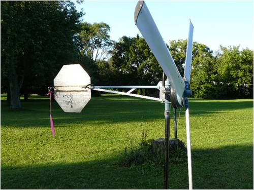
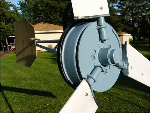
Jim |
||||
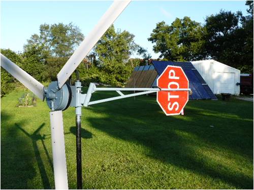
fillm Guru Joined: 10/02/2007 Location: AustraliaPosts: 730 |
Hi Jim That is all coming together very nicely , the good thing is you are putting some thought into the project to make it look good and neat, also be functional when it finnaly gets up , I see you trashed the stop sign in the last photo , a good looking tail and a nose cone will give the neighbours nothing to whinge about .. Keep up the good work PhillM ...Oz Wind Engineering..Wind Turbine Kits 500W - 5000W ~ F&P Dual Kits ~ GOE222Blades- Voltage Control Parts ------- Tower kits |
||||
| JimBo911 Senior Member Joined: 26/03/2009 Location: United StatesPosts: 262 |
Phil Always good to hear from you. Your help, advice and knowledge on my mill build has given me a scene of comfort and also allows me to think that this thing is going to work and work well. No wind around here (of course) but I have an idea. About three miles from here is a land fill that has since been filled up and is now open to the public as a scenic over view. My girl and I took a ride there to see if it would be a good place for a test site. Tell you what this hill has to be 100 feet higher then any trees and there are NO obstructions what so ever. It was a clear day we could see down town Chicago and that's about 25 miles away. I am making up a test rig to test my mill on top of that land fill can't wait to see the look on peoples faces. Honestly I am already getting a little nervous but excited as well. If all goes well I will post some pictures to keep all informed. Thanks again for your interest and your help. Jim |
||||
| JimBo911 Senior Member Joined: 26/03/2009 Location: United StatesPosts: 262 |
Ok guys here's one for you. Here in the states we have what they call The National Tour of Solar Homes it's on October the 3rd Saturday. People who wish to see sustainable energy systems are welcome to visit homes that are open to the public and of course yours truly will have his home open and ready for the tour. Last year during the course of a day we had about seventy people visit my place. I belong to the Illinois Solar Energy Association which promotes the tour in my area. It just so happens I had a news reporter stop by to interview me and check out my system, recognized that sexy looking mill in the photo. Yes I did tell they about the Back Shed web site and I will be telling all the folks that stop by about it as well. I guess its the big time for us mill guys!! 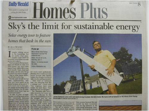
Jim |
||||
| Jarbar Senior Member Joined: 03/02/2008 Location: AustraliaPosts: 225 |
Jim,a fantastic effort. Would it be possible to send me a copy of your Daily Herald as I will be attending the local environmental festival in a couple of weeks.It would be a great example to help inspire others.And anyone in the forum who's local enough come along,I'll see you there. http://www.knox.vic.gov.au/Page/Page.asp?Page_Id=197 Regards Anthony of PVC Blades. "Creativity is detirmined by the way you hold your tounge".My Father "Your generation will have to correct the problems made by mine".My Grandfather. |
||||
| The Back Shed's forum code is written, and hosted, in Australia. | © JAQ Software 2026 |
