Notice. New forum software under development. It's going to miss a few functions and look a bit ugly for a while, but I'm working on it full time now as the old forum was too unstable. Couple days, all good. If you notice any issues, please contact me.
GWatPE Senior Member Joined: 01/09/2006 Location: AustraliaPosts: 2127
Posted: 05:44am 24 Oct 2009
Copy link to clipboard
Print this post
Hi oztules,
Am I correct in assuming that each line in the FEMM simulation represents a certain number of flux lines. The example above shows that 3 out of 11 lines leak without passing through the stator. This is a higher proportion than I would have expected. This would be like weakening the magnet by the same amount I suppose.
I expected that motor conversions overcame the leakage flux problem.
Gordon.
become more energy aware
Smart Drives Senior Member Joined: 06/07/2009 Location: AustraliaPosts: 115
Posted: 06:57am 24 Oct 2009
Copy link to clipboard
Print this post
Thanks, The graphics help a lot. slowly but surely all the info is sinking in , its a big learning curve though.
All smart drive parts sold
Custom built turbine parts on
Multicam flatbed CNC Router
oztules Guru Joined: 26/07/2007 Location: AustraliaPosts: 1686
Posted: 07:52am 24 Oct 2009
Copy link to clipboard
Print this post
Gordon,
This one was an example one I think, and the gap was probably widened so that all possible routes would be represented by the Femm diagram. I would doubt that too many motors have a gap the thickness of the magnets.
If the gap was reduced to sensible size, in this orientation, there would be little leakage I would think.
Just when the flux is jumping between teeth.... tooth to tooth, (slot ripple in a genny?) there will be all sorts of intermediate leakage mess I would suspect..... but I don't know for sure.
Hmmmm,
I don't know German, but I think I found the closed gap Femm.
Here the rotor leakage has been tamed, the intermagnet leakage has been reduced, but now the intertooth leakage has erupted because of the amount of flux lines trying to all get into the teeth/armature proper has created a bottleneck, and a few have bailed out early and made their way home via the next tooth, across the gap, through the next magnet, through the magnet case steel, and back to base...
It can get messy in there......change one thing and create new problems... but it will work better than the wide gap versions..... look at the flux colour/levels in the teeth.
Hehe, I can just imagine what happens when we wrap a few turns of wire on the armature, load it up, and get some reaction happening..... there'd be some leakage going on then... magnet to magnet, and magnet to rotor...........hmmmmmm.. Herb territory here....
..........oztulesEdited by oztules 2009-10-25Village idiot...or... just another hack out of his depth
GWatPE Senior Member Joined: 01/09/2006 Location: AustraliaPosts: 2127
Posted: 12:02pm 24 Oct 2009
Copy link to clipboard
Print this post
Hi oztules,
There is something funny with the FEMM, between the two examples. The magnet strength appears to be similar. same colour, and number of lines, yet the field in the return path is much stronger, by the colour. ????
I will stick to making prototypes.
Gordon.
become more energy aware
Tinker Guru Joined: 07/11/2007 Location: AustraliaPosts: 1904
Posted: 01:50pm 24 Oct 2009
Copy link to clipboard
Print this post
Gordon, look at the faint colour between the magnets in the first example, they are less pronounced in the second. Its not just the black lines which, IMO, just represent the path, not the strength, of the magnetic field.Edited by Tinker 2009-10-25Klaus
oztules Guru Joined: 26/07/2007 Location: AustraliaPosts: 1686
Posted: 10:54pm 24 Oct 2009
Copy link to clipboard
Print this post
Hmmm,
They way I look at it is this. Yes the lines represent the flux lines (or multiple of), and the colour the strength as you suggest.
If we start with X lines in the magnet, representing the entire flux component, it radiates from a given surface area. This will give us a quotient of lines per unit cross section area.... or flux strength if you will.
It stands to reason that if we restrict the cross section, we will have to squeeze more lines into a smaller area... hence the flux quotient will be greater in these areas...... darker colour.
Note, as the flux lines pack into the tooth, trying to squeeze down the leg, they bunch up in the center, and some head off to the tooth extremity (upwards). We can see how the same number of flux lines (I think it's 5) changes the background colour as the section area diminishes towards the tooth end. Where ever the lines/unit cross section changes, there will be flux changes, or where they may bunch up sort of staging to make a run for a good flux path.
The legs in the tooth are purple because of the number lines compared to the differing cross sections. Interesting how the purple changes to yellow again, as the flux splits up as it reaches the armature boss area, and goes two ways. The flux lines are halved, as is the intensity denoted by the colour.
Now, the difference between the two pictures is that the large airgap in the first and the skinny one in the second,... Here the guess work kicks into top gear.
If the gap went from say 2mm to say 12mm I would have said we had increased our air gap by 6 times, and so with the r squared of magnetic fields, would once have said that we reduced the force by 36 times. This turns out to be false. It appears that the gap is from the center of the magnet to the face of the tooth, and so from these pics, perhaps we went from 12mm+12/2mm=18mm for the wide one, to 2mm + 12/2mm=8mm. (gap+ 1/2 magnet depth)
So at first blush, it was a huge difference, but in reality I suspect it is only about (18/8) squared or about 5 times. So the useable flux from the first pic is about 1/5th the intensity of the second.... hence the colour change is more vivid.
The problem I have with this, is the lines in the magnets are consistent, the lines crossing the large gap is only 12 from 18, and the tight gap from 17 from 18...... so 1/5th intensity seems wrong as well .. seems more like 2/3 intensity.
Or they just changed the gradient standard
but I'm open to other interpretations
...Maybe Dinges or Sparweb (Femmers at large) will be better at unraveling this.
..............oztules Village idiot...or... just another hack out of his depth
GWatPE Senior Member Joined: 01/09/2006 Location: AustraliaPosts: 2127
Posted: 03:00am 25 Oct 2009
Copy link to clipboard
Print this post
Hi oztules,
I may go back to some earlier FEMM examples posted by dinges, and check the scaling colours. The extra indicated field strength in the magnet backing return path was what I was questioning.
Gordon.
become more energy aware
Smart Drives Senior Member Joined: 06/07/2009 Location: AustraliaPosts: 115
Posted: 02:04am 27 Oct 2009
Copy link to clipboard
Print this post
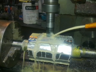
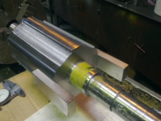
Here are the finished pics of the rotor.
We slid the magnets in just to double check the slot was the right width.
We had made the slot about 5mm deep , to make sure i didn't lose much power the diameter of the shaft was lathed down 2mm. leaving a 3mm slot.
Now comes the fun part EPOXY.... Edited by Smart Drives 2009-10-28All smart drive parts sold
Custom built turbine parts on
Multicam flatbed CNC Router
SparWeb Senior Member Joined: 17/04/2008 Location: CanadaPosts: 196
Posted: 06:38pm 27 Oct 2009
Copy link to clipboard
Print this post
Here, let's see if this will help. Peter's the man with the graphics in this arena, but maybe mine are good enough for this. I've included the scale in case anyone is curious, but it doesn't really matter in the discussion. Just look for the squiggly field lines and you can judge the intensity of the field by the colour scale.
This is one quarter of the cross section through the rotor and stator of my Toshiba conversion. Bigger than SmartDrives' conversion, but scale up or down it all looks about the same.
In this quarter section, you can see four magnets. The two on top are half of a "N" pole, the two on the side are half of a "S" pole. To see the whole rotor, you can imaging a mirror image to the side and to the bottom. The whole rotor has 12 magnets around the circumference. Because it is so big, there was room for 3 of these magnets per pole. On yours I see there is room for 1 mag per pole on the circumference, and 2 along the length. Those are big magnets - you have lots of potential there (haha sorry for the pun).
The N magnets send their imaginary lines of flux up into the stator, because the iron in the stator attracts them. They "flow" around the stator to the S pole and they pass back through the teeth there, jump the gap, and into the S pole magnet. The circuit is complete when they pass through the solid iron rotor to the bottom of the N magnet again.
In your case, SmartDrives, each pair of N and S poles of your rotor are only 60 degrees apart, unlike this 4-pole rotor, where they are 90 degrees apart.
Whether you're getting all this or not, it looks like you're on the right track with that rotor. If I was trying to make it "perfect" I would look for a set of magnets that fills up the pole as tightly as possible. "Cover the rotor with magnets" is my new philosophy!Steven T. Fahey
GWatPE Senior Member Joined: 01/09/2006 Location: AustraliaPosts: 2127
Posted: 09:41pm 27 Oct 2009
Copy link to clipboard
Print this post
Hi Steven,
Covering the rotor with magnets is the philosophy used on Pacific Scientific brushless servo motors. Essentially the same config as a motor conversion, but with curved samarium/cobalt magnets and a smaller rotor dia.
The coloured FEMM scaling is close to only a 10% change for each colour change, so this explains a lot. Visually indicates a small change clearly.
In your Toshiba example, I think the same polarity magnets would be better to be effectively be 1 large magnet face per pole.
Gordon.
Edited by GWatPE 2009-10-29become more energy aware
I am new to the forum- so excuse stating the obvious etc. I used to be a motor winder, first because the stator is AC (cant use solid iron) I would stay with laminations on rotor. It is feasible to melt out the cast aluminum rotor bars and shorting ring and leave vacant slots, are there rod neodymium magnets that would engage in the slots? I would guess that maintaining the min air gap and the existing lamination core is worth a try. Prior to meltout fit locking ring and tab weld at lower end of laminations (vertical melt out) unless they are pressed up to a spigot-- they will fall off otherwise. After meltout cautiously fit threaded rod with nuts to secure laminations from rotational displacement. Heat only as much as required. Reply comments invited.Bibi
Smart Drives Senior Member Joined: 06/07/2009 Location: AustraliaPosts: 115
Posted: 08:37am 28 Oct 2009
Copy link to clipboard
Print this post
"SparWeb, If I was trying to make it "perfect" I would look for a set of magnets that fills up the pole as tightly as possible. "Cover the rotor with magnets"
Hmm....Do you think that those extra magnets would make a significant difference ? Its just that i am so close to finishing that waiting for more magnets might drive me nutty....
I have bought some epoxy that is a paste, no need for a cage to hold it in place. The guy said a little bit on your but and you could hang from Sydney Harbour bridge !
It is important to buy an epoxy that can be lathed when fully cured, the cheaper ones might not be able to be lathed.
BRAND of epoxy is Epirez 633 NON-SAG expoxy binder.
compressive strength 85 MPA , tensile strength 12 MPA
Hi Bibi, Welcome..Its a whole new topic what you have mentioned.
Does someone have/know a link that shows the difference between leaving the laminations on the rotor and making a steel one ?
Thanks.
Cam.
All smart drive parts sold
Custom built turbine parts on
Multicam flatbed CNC Router
oztules Guru Joined: 26/07/2007 Location: AustraliaPosts: 1686
Posted: 09:43am 28 Oct 2009
Copy link to clipboard
Print this post
Bibi,
Welcome to the forum. Nice to have a motor guy on board.
The induction motor used as an alternator is a different animal to an induction motor. The stator needs to be quality laminate to avoid too much eddy current action from the fluctuating magnetic fields. The modified rotor on the other hand needs only to conduct the fluxlines between magnets, and these are for most purposes, static. Sop the rotor can be solid, as strong fluctuating fields are not of any consequence.
There will be modulation of the return lines from slot ripple etc, but on a tiny scale compared to the static fields. Armature reactance will modify the return lines as well, but apart form the windmill running away in current limit mode, I haven't heard of any problems attributed to eddy currents from this behaviour.... just the runaway..... which can be problematic.
Simple iron drag on the stator is the most serious issue (from the startup perspective), and cogging if not designed well.
It is unlikely that melting out the rotor bars will help any, as the temperature to melt the alloy, will denature the insulating lacquer between plates, and render it as a block of steel anyway.... and that's not a problem either.... static field.
Smartdrives,
More magnet is better as it helps reduce the armature reactance a bit more as we add more magnet. Use all the saturation you can sensibly cram in to the rotor.
The difference between using the old rotor and making a solid one will depend on where the rotor bars were, and whether machining it down to where you want to go, makes the rotor fall apart or not....
The cavities from the bars (porosity) will not help, but on a big rotor, enough steel may remain to do the job of linking up the magnet flux pretty well.
Placing neo's into the cavities of the rotor bars will only result in poor use of magnets, as flux leakage will be rampant in this configuration. It will sort of work if the magnets are magnetised side ways, rather than longways, but poorly.... and would not address the cogging or pole placement nor magnetic bulk..... not worth the effort for useful power I suspect.
...............oztules
Village idiot...or... just another hack out of his depth
I hear what you say. On a minor point, meltout does damage the inter lamination "laquer" but not critically. We have done it to replace poorly cast Al rotor bars with silicon copper on a hi torque start motor- a close coupled centrifuge. Separation and oxide layer for elimination of eddy currents is OK. In the good old days, the laminations were punched, acid bathed to form an oxide layer before random jigging up. This whole exercise is prompting me to look back at genset rotors-- although critical design here was regulation and most of the plus or minus 1kva systems were 2 pole. Anything meaningful, I will post.Bibi
Smart Drives Senior Member Joined: 06/07/2009 Location: AustraliaPosts: 115
Posted: 08:29am 29 Oct 2009
Copy link to clipboard
Print this post
Ok looks like i will order another 6 magnets to fill the slots i have made. I have come this far waiting a bit longer wont hurt.
thanks.
Cam.
All smart drive parts sold
Custom built turbine parts on
Multicam flatbed CNC Router
SparWeb Senior Member Joined: 17/04/2008 Location: CanadaPosts: 196
Posted: 06:00pm 29 Oct 2009
Copy link to clipboard
Print this post
[quote]SmartDrives: Ok looks like i will order another 6 magnets to fill the slots i have made. I have come this far waiting a bit longer wont hurt.
[/quote]
Wait - there is something you can do first before comitting to more magnets. I guess if I say "here's how to do it better" I should expect people to try to do it, but in life, nothing is ever perfect. There's a lot of good enough.
Here I am making all kinds of suggestions, but you have the real thing on your bench and all you have to do is give it a spin to know if you're doing things right!
So why not assemble the rotor and stator, as they are, and see what you've got? You have the magnets glued on the rotor, I suppose, which is good enough to keep them in place for an insertion, run-up, and removal afterward.
[quote]Gordon: The coloured FEMM scaling is close to only a 10% change for each colour change, so this explains a lot. Visually indicates a small change clearly.
In your Toshiba example, I think the same polarity magnets would be better to be effectively be 1 large magnet face per pole.
[/quote]
I carefully set the scale of the colours (you can do that in FEMM) so that the numbers were easy to relate to the colours. I had made several different models of Toshi before converting it, but the outputs were hard to compare. I made the three models' colours scale the same so that I could hold up all three and pick which set of magnets would be best.
Of course I'm limited by the choices of magnets available. A curved magnet with a 5" OD would have been perfect, but you can't just buy one. You pay 1000 dollars a piece or you order 100 from China for 20,000 USD.
On retrospect, I could have made my Toshiba conversion even better, by making a new solid rotor instead of using the laminated rotor. That, too, would have been more costly.
Steven T. Fahey
Dinges Senior Member Joined: 04/01/2008 Location: AlbaniaPosts: 510
Posted: 06:42pm 30 Oct 2009
Copy link to clipboard
Print this post
Have you taken measures to prevent cogging of your rotor?
Peter.
Smart Drives Senior Member Joined: 06/07/2009 Location: AustraliaPosts: 115
Posted: 09:55pm 30 Oct 2009
Copy link to clipboard
Print this post
Hi Dinges,
Yes, i have had the slots in the rotor angled at 10 degrees. I have decided not to test the magnets i have as i am afraid of breaking them when i remove them. I am going to order some smaller ones to fill the slots as much as i can.
Thanks.
Cam.
All smart drive parts sold
Custom built turbine parts on
Multicam flatbed CNC Router
Dinges Senior Member Joined: 04/01/2008 Location: AlbaniaPosts: 510
Posted: 11:32pm 30 Oct 2009
Copy link to clipboard
Print this post
Ok, was hard to see in the picture whether the slots were skewed or not.
Not sure what the problem is with the magnets, looks fine to me. 2/3 of the rotor circumference is covered - can't get any better than that.
Peter.
Smart Drives Senior Member Joined: 06/07/2009 Location: AustraliaPosts: 115
Posted: 06:00am 31 Oct 2009
Copy link to clipboard
Print this post
There isn't a problem with the magnets but it was mentioned that more magnets are better, I was going to test the ones i already have but was afraid of breaking them when trying to remove them after the test. So i am waiting to see if frenergy has the same width magnet but only 25mm long to fill the rest of each slot.
Cam.
All smart drive parts sold
Custom built turbine parts on
Multicam flatbed CNC Router
Page 2 of 4
Print this page
The Back Shed's forum code is written, and hosted, in Australia.