
|
|
Forum Index : Windmills : - NEW ALUMINIUM BLADES -
| Author | Message | ||||
SparWeb Senior Member Joined: 17/04/2008 Location: CanadaPosts: 196 |
Peter and Oz both have very important things to say, but in all the detail of the explanation they give, the critical instruction is lost: If you're going to mount that blade to the hub with a tube, the tube has to go the WHOLE way out to the tip. The mounting tube is the structural member and it must resist radial tension, bending and twisting all at the same time. Don't expect the plastic or aluminum extrusion to withstand any of that. The material of the blade doesn't make the slightest difference. I was dumbfounded to see anyone using short little stubs in the plastic airfoils. How much does a few meters of 25mm rod cost in AUS? It's darn cheap here. Now you're shelling out for 4140 steel. This is your problem: 
Stop doing that. Steven T. Fahey |
||||
| Dinges Senior Member Joined: 04/01/2008 Location: AlbaniaPosts: 510 |
Steven, You make some important observations, but there's one important thing still missing from your drawing. You do round the ends of the steel bar, but that's not enough - there's still a very large transition from a solid steel bar to a (hollow) pipe, causing practically all stresses to concentrate into a small area (see blue arrow). One can predict with certainty where that blade will fail: at the blue arrow. With or without a fillet - it makes no difference. I suppose you too know that adding material (i.e. making some parts stronger) can actually cause it to fail sooner, rather than later. 
The only solution I see is to *very* gradually transition from solid bar into hollow pipe, by drilling a cone into the solid bar. Not easy though. A completely solid bar through the *entire* blade (very important, as you say) would probably be much easier, but that would leave a lot of (unnecessary) material at the tips and thus be heavy. And I'm still not 100% convinced that it'd relieve all fatigue problems, as there will likely be torsional modes of vibration too, and more complex forms. If something similar to wing flutter were to occur, all bets are off anyway, no matter how big/large/heavy/strong you make it. The remarks about adding a few rivets/bolts to 'help' or 'insure' the adhesive bond is plain silliness. It contributes absolutely nothing and will likely actually weaken the construction by adding stress points where cracks may initiate. That's the beauty of an adhesive joint. And as for strength... 25+ N/mm^2 should be easily achievable. 50-60 N/mm^2 is achievable with good epoxies. Taking into account the surface area for glueing (pipe 25mm dia, length, say, 1m; assuming half of the surface area is used (see contour alu extrusion profile) that's 40000 mm^2; at 50 N/mm^2 (shear) that's 2.000.000 N, or 200.000 kgf (for a 1m long blade). Yes, 200.000 kg. But, feel free to add one or two extra M3 screws, 'just to make sure'....  Btw: the previous deals only with static shear, not with fatigue. Btw: the previous deals only with static shear, not with fatigue.
Those plug welds don't have to be an issue either, as long as you make sure all residual stresses and carbides are removed by a proper heat treatment afterwards. There's nothing magical or radically new in anything I (or you, Steven) have said - all this stuff has been known for 50-60 years in industry. There's a reason there are autoclaves, different welding techniques, preheating, postheating/cooling, heat treatment regimen, surface treatments (shot peening), etc. to solve the problems us amateurs are getting into by trying to use steel/aluminium blades. As said before, I think I'll stick with wood. Much easier to get good results with wood for a simple sod like me. Peter. |
||||
| SparWeb Senior Member Joined: 17/04/2008 Location: CanadaPosts: 196 |
Peter, the drawing isn't mine. It was taken from Homegrown power's website. You can find it yourself from the home-page and clicking on the "kits and parts". It's the first time I went looking for the page myself, because previous discussions I thought people were just making up their own mounting. Now I see that HGP is suggesting this. Gizmo / Jarbar: Sorry for this - it's not a deliberate bashing but I am on a roll today and if you care to correct the problems that Peter is pointing out to you, then we can put the guns away. You can either take our suggestions, or hire a local engineer to work out the details for you because there are some dangerous details to be worked out. Steven T. Fahey |
||||
| Gizmo Admin Group Joined: 05/06/2004 Location: AustraliaPosts: 5187 |
OK, this is getting messy. First up, thebackshed has nothing to do with OEM and the PVC/Aluminum blades other than providing the web space for Anthony and Phill to advertise their blades. The drawing shown on th PVC blade page is how I made my blades. At the time I thought it was overkill, but I like making things stronger than I think they need to be. Some said it was too heavy, but I prefer a heavy turbine than a broken turbine. My windmill with the PVC blades has been up since day one, several months now, and through several storms. Its working fine. The original OEM prototype windmill design only used (very) thing wall tube, about 50% of the blade length, with no inner rod. Their blades fell off on several occasions I know of, and the PVC started to bend back permanently after the end of the tube. On this forum we've seen several builds using the PVC blades that, at construction time, the builder said would be strong enough, only to fail days/weeks after. Fact is, we are a bright bunch with abundant knowledge and experiences in many different fields, but we dont know what we are doing. I agree, a structural engineer with experience in turbine ( propeller ) design, and insurance to back them up, needs to come up with a design that will make these blades safe. Safer than timber, or those Chinese fibreglass blades that fall off at a regular rate. Glenn The best time to plant a tree was twenty years ago, the second best time is right now. JAQ |
||||
oztules Guru Joined: 26/07/2007 Location: AustraliaPosts: 1686 |
Stephen: [quote] Peter and Oz both have very important things to say, but in all the detail of the explanation they give, the critical instruction is lost: If you're going to mount that blade to the hub with a tube, the tube has to go the WHOLE way out to the tip. [/quote] I thought I covered it here: [quote] A solid rod/ heavy wall tube right up the middle with an end cap, means that the blades cannot fail, and cannot fly off. Torque forces from twist are feeble, and the center rod takes all the forces, the blades are just along for the ride...... so much for the anti aluminum argument... just design it out The weak link is then the steel rod..... and if the mill is kept to a reasonable diameter, and the rods mounted with thought, should last forever as well.... the Al blade cannot get away... even if they were to fracture and crack/split [/quote] Weight is not a problem, so solid all they way is the best I feel. Whatever system is used, providing the aluminium is designed out of the stress loop, and only goes along for the ride, .... it cannot contribute to failure..... Concentrate on the steel bit, that will be only reason for failure.... and it can be solved easily with sensible design. ...........oztules Village idiot...or... just another hack out of his depth |
||||
| SparWeb Senior Member Joined: 17/04/2008 Location: CanadaPosts: 196 |
You did Oz, But I was afraid that you didn't attract enough attention to it. Too often in long explanations the middle part doesn't get read by 1/2 the viewers. Steven T. Fahey |
||||
WXYZ Newbie Joined: 30/04/2006 Location: CanadaPosts: 20 |
The age old argument about aluminum or is aluminium. My experience with the stuff for windmill blades is very simple. For low power, small wing units it is a suitable material for moderate wind zones. BUT aluminum does not scale up well like other materials. The wind zone that I was in was hell on aluminum windmill blades. GUSTY, UNIDIRECTIONAL. The first failure that I had sent one of my 1.2meter blades 150 meters. I did not find it till the following spring. Yet aluminum blades mounted the same way one half the length have run successfully for years. Even so I like the blades. Joseph  "Failure is an option." |
||||
| Gizmo Admin Group Joined: 05/06/2004 Location: AustraliaPosts: 5187 |
I'm starting to agree the tube should run the full length of the PVC/Aluminium blade. Not only does this take the PVC/Aluminium structural strength out of the equation, its also gives us something structural we can attach the end cap to, and that will stop the blade sliding off the tube. I do think the inner rod should extend further than then 25% shown, but not the full length. When you think about it, using solid for the last foot of blade is serious overkill, and a lot of weight. The further out we go, the more the weight of the solid will have an effect on turbine acceleration, and gyroscopic forces that will affect the way the windmill tracks and furls. If we make the solid 50% of the blade length, with tube continuing to the end, would this be strong enough? At 50% the forces would be much less than at 25%, but how much less? This is where we need an engineer. I worry more about the hub than the blade. If we go for a solid rod, or even thickwall pipe, then the blade itself should be failproof ( knock wood ). But if the blade comes apart from the hub, then we have a steel rod leaving the scene at great speed. Now that can cause some damage! Fact is, the PVC blades do perform very well, as will the aluminium blades. Anyone who has used them will agree, and I for one wouldn't consider any other blade while these are available. We just need to sort out a mounting system with will be safe, reliable and economical, which I'm sure can be done. Glenn The best time to plant a tree was twenty years ago, the second best time is right now. JAQ |
||||
| brucedownunder2 Guru Joined: 14/09/2005 Location: AustraliaPosts: 1548 |
After I found my 2 ABS plastic blades ,I did notice that the breakage was across or inline with the bolts that attached the blades to steel stiffeners or steel plates attached to the hub . So, I reasonably think that it was this part that was weak,ER than the rest of the blade.. Bye the way , these blades travelled a good 250 Metres and surprisingly , there are NO dings or scratches on them .They could esily have been busted because of the enormous winds we had that night ,mind you they didn't hit the tower,,.. OK, so we get back to "point of attachment",, I'm fairly confident if the rod is solid for half the length then as others say hollow for the other half ,it would be fairly light and a bit flexable for the last half... Now , as Phill has said ,no welding at the root. He's got a very good handle on how to securely fix these and still allow rotation ,I've seen them. Bruce Bushboy |
||||
fillm Guru Joined: 10/02/2007 Location: AustraliaPosts: 730 |
I Agree and with gizmo , that a lot of what is being put forward here to do with design paramiters is very much out of the relms of what we/I are trying to achieve , that being to come up with a cost effictive , strong ,secure and safe way of mounting a set of Aluminium / PVC blades . Cost effective , I mean by not having to buy products like expensive special adhesives , chrome moly or cdw tubing , both of which I spent a day on the phone costing . When it came down to it 4140 solid was the same price as cdw tube but would still need the solid in it for the first 25% , the solid would be then turned down which would further weeken the root . I think 4140 is by far the strongest for its price for the load it has to bear . My objective is not to use welding at all , and to have an easy to assemble blade hub and spigot system . I have spent a lot of time designing making testing and scrapping ideas , one being the crimp clamp , but now the clamps will be the basis of the latest design and used as the main rod supports . Below is a picture of another I recently went down the road with , a highly strong individual mount machined out of a 1" JIC hydraulic fitting allowing the 36mm nut to lock the s/s tube while the 4140 solid as locked into a boss in the tube(cant be seen) as well as the collar , which would be a split collar and the bar under cut to suit , would not allow the bar to move out , and some one would say " what if the nut came loose" then the boss in the tube has a grub screw lock into another under cut in the solid , then what if the s/s flare lock let go , at 80% of the solid length a 6mm bolt would then lock the blade , s/s tube and the 4140 solid as one . See pics below , at 2 ton that is what happens to the bolt solid and tube ( I did not have a nut on and tight for the test , the flare did not budge , the boss is welded in and the idea was to slot the heavy walled 2" tube up to the boss and it could then be welded to any hub , ok for me , but the cost in machining says no for anyone without a lathe . 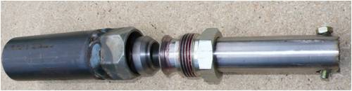
This was the origional with a 37 deg flare , scraped that , still good for 2ton+ 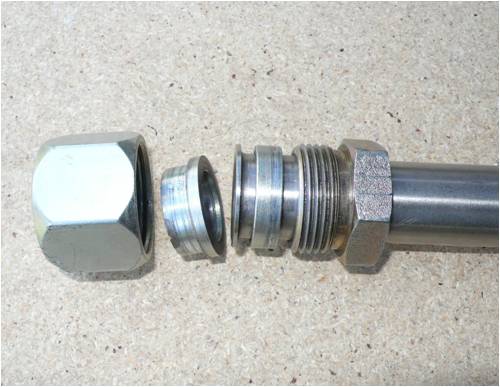
New flare 90 deg , makes machining the collars easy , again scrap , again good for 2T , but as you can see below the bolt starts to tear through the s/s tube at 2.2T 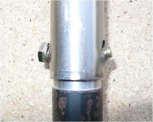
So onto the next clamp and tube now , and yes I do get a bit annoyed when all the advise on how and what to do and why , when no one has actually worked out what loads we are dealing with , how much centrifical force is exerted by a 4kg blade @ 1000 rpm and can they reach 1000rpm ,so why not set that as the bench mark , I've seen 780. How much axial forces are we dealing with in the gyroscopic forces wind forces furling/yawing forces at 75% in from the blade tip as well as at the root . Can it be worked out here on the forum in a constructive manner ? To throw another senero in to the thread , my origional set of 3.15D pvc blades which are still flying and have been subjected to every wind storm , even the one that destroyed the ax fx 3.2 set , have been out of controll yawing , furling violently and hitting 750rpm constantly on the F&P and are now on the Ax Fx and recorded the 3.2 Kw @ 550 rpm in 57klm during the last lot of storms . These mounted on 150mm solids with 800mm ss tubes plug welded , these are the same blades that started to elongate the rivet holes in the PVC . The plug welds are not located near the load point as was the blade that failed . That is greater than 90 / 10 leverage ratio and for all the axial forces and they have not let go YET , I think it is relevant when all we can come up with is , solid all the way , solid 50% of the length . With what I have seen in the load tests on the s/s tube, at any thing over 2T it deforms and this point would make me think that it should be tearing away from the plug welds or easily tearing the tube if the forces were greater than 2T at the load point of the solid to tube . Which gets me back to the question , How much force are we dealing with ? and is adding extra weight that is not needed only going to cause additional failure areas due to the increase in axial loadings ? PhillM ...Oz Wind Engineering..Wind Turbine Kits 500W - 5000W ~ F&P Dual Kits ~ GOE222Blades- Voltage Control Parts ------- Tower kits |
||||
| WXYZ Newbie Joined: 30/04/2006 Location: CanadaPosts: 20 |
fillm, and yes I do get a bit annoyed when all the advise on how and what to do and why Forum is what we have to show our work. I would love to get a set of those aluminum blades that are in the picture of your post. I would proceed some what similar to your approach, and yes I would get the same flak. I see many ways to attach those blades that would work flawlessly for many years and be cost effective too. Keep up the work. I have used aluminum blades for years and will continue to do so. Joseph "Failure is an option." |
||||
| frepdx Newbie Joined: 16/11/2009 Location: Posts: 7 |
As you mention below, choosing material and mountings is kinda difficult without knowing the loads. |
||||
| SparWeb Senior Member Joined: 17/04/2008 Location: CanadaPosts: 196 |
I can make a start, but plugging numbers into an equation doesn't replace understanding what's going on. The list of assumptions and data to be collected is long: Rotor Diameter (Blade Radius) Rotational Speed Total weight of aluminum extrusion Weight distribution of extrusion (at least it's constant in this case) Airfoil lift coefficient, pitch coefficient, drag coefficient (variables with angle of attack) Mounting tube cross-section (diameter + wall thickess) Mounting tube material + heat treat Subsequent machining to mounting tube (eg. holes drilled thru it) Retention mechanism of mounting tube Attachment fasteners of airfoil to mounting tube I don't think that's an exhaustive list but it covers the biggies. Since you have centrifugal, thrust, torque, and pitch twisting forces on any rotor blade, you have to assess all four and find the way to sum the forces. In addition, you must account for gyroscopic yaw and add that on top. Keep the sum of those loads below the fatigue limit of the steel tube/rod. Then there are the detail analyses of the rod attachment to the hub, airfoil attachment to the tube and you end up writing a report with a dozen pages or so. And then, it's only going to apply to the single case that was studied. So no, Phill, sorry, that doesn't work on an internet forum. Not when someone wants to sell a product and not have their A** sued off. It's much better to use this space to discuss ideas and share pictures of solutions, than to try to check each others' work in detail. Steven T. Fahey |
||||
| Perry Senior Member Joined: 19/11/2009 Location: Posts: 190 |
Hello fillm, A few comments. First off, interesting thread. Secondly, I do not feel that this is a terribly hard problem to model if you can give us a few of the parameters. You have a few things working for you here that makes it not a dire circumstance. Primarily the fact that you have a constant chord, no twist blade. Moment of inertia is constant for the blade and center of mass is easy to find. Some free body diagrams for the individual components will help to identify the reactant forces and vector sums can be taken to give an overall picture. What I am saying that there are a lot of posts here saying the math is impossible and the forces too complex to figure out but I don't agree. We can start with a simple model and refine that. So to help let me question your beginning assumption. What is the weight per meter of the extrusion? Also, what size rotor dia do you want to use for your 1000 rpm test case? Frepdx's calculations above show the centrifugal forces for a 4 meter (13 ft)rotor dia machine. Would you expect a 4 meter machine to spin at 1000 rpm? Probably not. Also to comment on Sparwebs (with a name like that he should be able to calculate these things in his head) and Dinges' comments I think they are very thought out and pertinent but I might add that Otherpower and others sell wooden blades. Are you saying that they have gone through a critical review process of the mechanics and have the sh_t load of insurance that you are asking these guys to do? Just a thought. Answer the above questions fillm and we can get started bracketing the math a little bit. Perry |
||||
| SparWeb Senior Member Joined: 17/04/2008 Location: CanadaPosts: 196 |
Hi Perry, Thanks for bringing a positive voice to this. Maybe I'm approaching this will a negative attitude. I do prefer, in professional life, to challenge people's idea of how "easy" their job is, to put them into a more realistic frame of mind as I tell them how long and how expensive their project is actually going to be. I don't know what to say about the Otherpower blades. They look okay. I have seen some flimsy sheet-metal hubs, with no stiffeners, holding large-diameter blades. I don't go around doing stress analysis on every blade I see. But when someone asks about a problem, then I'm going to give my honest answer. Phill's misadventure could have been avoided if the seller of the blades had more carefully investigated the means of attaching them. I'm sure he's taking this criticism to heart right now and looking for ways to improve that. Impossible? Possible! I've done the math myself on my own blades. I found that the combined loads and structural stresses on the hub to be high but survivable in my assumed "runaway" condition. I also discovered that the gyroscopic moment can apply significant stress on the hub, so I am careful to include it any time the topic of discussion comes up. Maybe its not so important on a hollow blade, but then maybe torsion is more of a problem with such a cambered airfoil. More and more questions, so that's why I'm careful. Everyone makes mistakes. I examined a Korean-made wind turbine a couple of months ago, and I discovered some surprises. I could push on the blade tips with about 30 pounds of force and bring them almost in contact with the tower. The bearing support brakets were 1/8" thick sheet. Sometimes it seems like the lessons learned 100 years ago are being deliberately forgotten. It's happening in the airplane world, too. Don't fly inside a Boing 787, whenever they get delivered to the airlines. Never. Steven T. Fahey |
||||
| Gizmo Admin Group Joined: 05/06/2004 Location: AustraliaPosts: 5187 |
I dont know if I should take offence to that or not. Phill didn't build his turbine as per the recommended methode shown on the PVC page. Maybe if he had, it would not have failed. Sorry Phill, dont take this the wrong way, I'm sure you can see what I'm getting at. Phill is experimenting with different ways to mount the blades, and he had a failure, which he has learned from and will improve his designs. Now I ask, if anyone who did build their blades as per the diagram on the PVC page, and had a failure, could they let us know. I agree the gyroscopic forces when a windmill suddenly changes direction need to be taken into account, these forces are most likely the most severe of all. Glenn The best time to plant a tree was twenty years ago, the second best time is right now. JAQ |
||||
| fillm Guru Joined: 10/02/2007 Location: AustraliaPosts: 730 |
Hi Perry , Frepdx Thanks for your comments , and I welcome any input that you or others may have to contribute . Firstly I notice that it has been mentioned that this is some kind of misadventure in taking these on to distribute these blades , I am not sure of what this is trying to say , firstly I believe this is a good blade and at an affordable price , weather this profile is in wood,pvc or aluminium in my experience thus far it is a winner ,so am I going to be able to retire a wealthy aluminium blade tycoon in 1 year selling these to a handfull of .1% of the population of australia , I don't think so . Some here may think so ! In the mean time I will have to keep working for a living 
The pvc version is no longer built so if anyone wants them Anthony/Jabar still has stock and cheaper than these will be . Now back to the mounting , and the answer to Glenns statement is , Yes, the blades would still be on if I had followed the mounting proceedure outlined here, But I will add that the root cause of that failure was the incorrectly positioned plug weld , but does this mean that we should now just because these blades are aluminium increase the solid to 50% or 100% . Perry , the reason I picked 1000rpm is because of a run away situation , an aluminium blade 1.5m weighs 1.75 kg , if the blade is mounted on a 250mm would give a dia 3.250 (dia of the blade that let go) . For the test case I would pick 3.1d as I know now that this can deliver 3.2Kw at 550 rpm in 55+Klm . I would stick to 22mm solid 4140 25% of 1.425 of blade length and 25.4 x 1.2mm s/s tube to 75% . Feel free to round it back to 3m dia and a 4kg total blade mass, I do not know the weights exactly for each , at present I am 2000k away from my home . Getting back to the points I made previous , the s/s starts to tear and fail at 2T , thats a lot of weight , equal to a 4wd wagon exerting radial or axial load , I really can't see those forces being generated at 25% out from the root in a 3.1m dia blade set when its not getting there at a 125mm load point , mabe consentrated at the root in extreem conditions. The mount as I have said is solid and easy , its the extensions out from that which is the unknown and the further you move the weight the more it compounds at the base . If you went to solid all the way in 25mm normal steel it might appear solid but if you put one end in a solid clamp / vise and sat on the end at 1.25m it will bend with minium force at the vise very easily , gyroscopic force could easily exert 80kg at the root I would think. As has been said and I am of the same opinion , let at least the end 25% be unsupported , do we really need to be adding weight out there. If its the blade flying off that is concern then an internal strainer wire cable with crimped threaded ends to a solid aluminium end cap and screwed into the solid would be a lightweight strong solution I have thought about for a while after the rivet holes started to elongate in the pvc , but scraped that idea as a few extra rivets can easily carry the load and is by far a cheaper solution . Which comes back to the question , how much force are we dealing with at a given weight mass and rpm then mulyiply it by 2 or 3 and design it to suit . The same principals go into lifting equipment , eg- chains , slings and their rated loadings. PhillM ...Oz Wind Engineering..Wind Turbine Kits 500W - 5000W ~ F&P Dual Kits ~ GOE222Blades- Voltage Control Parts ------- Tower kits |
||||
| Perry Senior Member Joined: 19/11/2009 Location: Posts: 190 |
Phill, I think there is enough information there to get started on some calc's. I'm off to Boston for the weekend but I will try to get to it. Perry |
||||
| Jarbar Senior Member Joined: 03/02/2008 Location: AustraliaPosts: 225 |
Quote"so am I going to be able to retire a wealthy aluminium blade tycoon in 1 year selling these to a handfull of .1% of the population of australia , I don't think so . Some here may think so ! In the mean time I will have to keep working for a living"Quote. Yes the PVC blades have proved to be a great addition to windmill fraternity and resource via this forum.It has also been something I was passionate about.From the original introduction of the potential manufacturer OEM and helping them and Glenn with design and development.I was then, what I thought unbelievably lucky to be asked if I wanted to market them.And any risk that might come with them at that stage of development. With Glenn's help and predominantly members of the forum who have bought and tested them proved that for a reasonable price a good quality product was available versus spending hours cutting some out of wood.I have supplied PVC blades to all corners of the Globe and have had very positive feedback.Yes their have been a couple of failures to which I have responded with replacement blades even if it was the builders fault.We can all make mistakes,it's how we learn and the greatest value of this forum. I was then asked by OEM to only supply Australia and New Zealand as they had the rest of the Globe covered and diligently sent blade requests on to OEM.I was aware of and also encouraged the development of the Aluminum blades although some had misgivings. I was hoping that efforts to this point would be rewarded with continuing developments in the Aluminum that they too would be available through me.For some it may only be small beer but for me on a pension chronically ill and with four children under 12 it was one ray of hope for some supplementary income.Other's too have been left out of the loop but I'll let them speak for themselves. Yes I still have the PVC blades but once gone what then? I apologize profoundly to those that waited longer than necessary for their orders but thank them sincerely for the hope and sense of achievement they helped give to me.I still intend to get better and PVC blades are still available. I wish OEM and Phil the best outcomes with their/our Aluminum blades.And thank all members of the forum for their invaluable input. Anthony. "Creativity is detirmined by the way you hold your tounge".My Father "Your generation will have to correct the problems made by mine".My Grandfather. |
||||
Downwind Guru Joined: 09/09/2009 Location: AustraliaPosts: 2333 |
Talk about placing the cat amongst the pigeons!! Firstly, good on Dinges for stepping up and throwing the negatives into the arena. 
Secondly I think Oztules hit the nail on the head with there will always be problems but design them out.
Lets face it nothing is idiot proof. 
I question the use of stainless steel for the tube. What great benefit do SS give? Is harder for the average home constructor to work with.( and more likely be substituted for an alternative ) Is there any real gain in strength with SS?? SS looks good but has many shortfalls to me as a good choice of material to work with, and to do a general design around. I put forward a thought not yet discussed. I’m sure most of you with a F&P have heard a wind down or wind up sound emitted from the mill. This sound is a vibration or a frequency emitted, Place your hand on the tower or the guide wires and you should also feel it, its effect is everywhere. I would think this vibration would also be emitted out through the blades and the ally skin would also be effected by this. One thought would be fill the blades with expanding foam once assembled. This might have some effect on balancing afterwards though. The foam would keep critters etc. out and to help reduce any isolated metal fatigue. I would not think it to be a strength improvement but to assist in an area that might come into play with F&P generators. Repetitive vibration is often over looked and we see mainly the mass effects but the smaller vibrations (elongation of rivet holes etc. ) cause fatigue and the mass loadings then tear it apart. As Oz said! Design it out! Pete. Sometimes it just works |
||||
| The Back Shed's forum code is written, and hosted, in Australia. | © JAQ Software 2026 |
