
|
|
Forum Index : Microcontroller and PC projects : Proto Board for the uMite 28
| Author | Message | ||||
| paceman Guru Joined: 07/10/2011 Location: AustraliaPosts: 1329 |
Hi Zonk, Not sure which 3.3v reg you're thinking of but it might be worth looking at the Microchip TC1262 low-dropout one that Geoff used for the ColorMaximite design. (Silicon Chip, Sept 2012, page 28) His article noted that it had a good LDO and better, that it had a very accurate 3.3v output - within 0.05% of 3.3v. The accuracy is important because analog-in readings are referenced to the supply voltage. Accuracy will probably be important to a few embedded uMite applications and even if your board is targeted for development, anyone who wanted to know what sort of analog reading accuracy/precision they might get from a uMite system, without having to put in fancier voltage reference stuff, would then know from your board. Greg |
||||
donmck Guru Joined: 09/06/2011 Location: AustraliaPosts: 1314 |
Please forgive me if I am misinterpreting your PDFs Zonk, but no mounting holes? Don... https://www.dontronics.com |
||||
Grogster Admin Group Joined: 31/12/2012 Location: New ZealandPosts: 9975 |
@ paceman - yes, the 1262 would be a good choice here. I always like the MCP1703 series regulators, which are also LDO. I would have to have a quick gawk at the PDF for the 1703's to find out about their voltage accuracy - the 1262's could be better in that respect... @ Don - Correct. The PCB is designed to be self-supporting, when you plug it in via it's I/O edge-connector or IDC type connector. It is small and light enough for that, but mounting holes would have been a bonus - not sure if there is any way that can be squeezed in now though!  Smoke makes things work. When the smoke gets out, it stops! |
||||
| paceman Guru Joined: 07/10/2011 Location: AustraliaPosts: 1329 |
The spec sheets are one thing but Geoff noted that the on the samples he checked the output of the 1262's was within 0.05% of 3.3v, whereas the spec sheet quoted 0.5%, i.e. 10X worse. Guess Micro Chip are being very conservative but that might not be true of all manufacturers with their specs. Greg |
||||
| Zonker Guru Joined: 18/08/2012 Location: United StatesPosts: 772 |
Thanks everyone for the suggestions on the regulators used on the board..! The TC1262 seems to be perfect fin for the AUX 3v reg as its the "in-gnd-out" type and matches the footprint I have in place. (sweet).. Originally, I had planned on using a separate 3v reg for just the MPU and Rs-485 chips. I am going to change the footprint for the T0-92 local regulator to match the MCP1702 part for this. It seems to be a +/- 0.4% voltage accuracy needed for the uMite. I thought that having two regulators on board would allow the user to draw more current to the outside while isolating the "inside parts" on there own source. Not sure if everyone out there thinks its worth the extra space on the board... @ Don.. Thanks D for chiming in on this thread..! I was not thinking correctly about the need for mounting holes as this was to be a prototype thing, but hay, I guess, why not... Was you idea to possibly use this as a platform type unit..? You could fit a 26 pin female connector onboard and then put a expansion board on top.. (or bottom)... Sure... Would putting 4 mounting holes in the corners be ok..? It would make the board bigger, but if the end user didn't want them, you could just "saw-off" the part with the holes on it... Ok.. I will update the artwork during the weekend and spin up the gerber files for posting... Again.. Thanks everyone for helping to get this thing done..!!  |
||||
| Grogster Admin Group Joined: 31/12/2012 Location: New ZealandPosts: 9975 |
You have a point there... Out of interest, I might check the output voltage on several of the 5v 1703's I already have on assembled boards, and see what they measure as. Smoke makes things work. When the smoke gets out, it stops! |
||||
bigmik Guru Joined: 20/06/2011 Location: AustraliaPosts: 2981 |
Gday Zonker, Join the club... I have designed many PCBs for Don in the past and almost always he comes back with "where are the flaming mounting holes.. Sonny??" SO that brought a smile to my face.. I assume that you use an auto router so you should be able to squeeze the holes (3mm) into the corners and move a few components to clear them.. Personally I like a smaller PCB rather than a larger one (esp if its just for mounting holes). Whilst it is tight there is still some room to squeeze tighter (gap between resistors can be tightened to 0.1" - They look like 0.15" and they can be 0.3" axial instead of 0.4" axial... And for that matter they can actually be vertical mounted so only take up a 0.1" foot print, 1/8W resistors can even be called for and they only need 0.2" axial footprint. Also what is your idea with the PCB edge connector below the 26Way header? Do you really need that? If you move the 26way header down a bit and remove the edge connector then there is some room to shift some components between the 26way and the Pic32... If your idea is to use the edge for (vertical) mounting then install a R/A 26way header for that purpose. Great work on this design it looks fantastic and I want a few. Regards, Mick EDIT** Also if you think its still too tight you could delete the PTC resettable fuse. My 2c worth, please dont take it as anything but CONSTRUCTIVE criticism. Mik Mick's uMite Stuff can be found >>> HERE (Kindly hosted by Dontronics) <<< |
||||
| Grogster Admin Group Joined: 31/12/2012 Location: New ZealandPosts: 9975 |
Yes, once the PCB is final, I definitely want a couple too, although I may be more interested in the 44-pin QFP version of this design... Smoke makes things work. When the smoke gets out, it stops! |
||||
| Zonker Guru Joined: 18/08/2012 Location: United StatesPosts: 772 |
Yep... I guess your right here Mik... I didn't think about the possible use as a small platform board too... I will scrap the layout and have and have a go again with the holes this time.. I like your idea of using smaller parts.. Was trying to keep it easy to build using the through hole parts... BTW, it was all hand routed,... (I hate most auto routers) They can never seem to get small boards finished... Looks like this will take a few more days... Thanks Gents.. |
||||
| bigmik Guru Joined: 20/06/2011 Location: AustraliaPosts: 2981 |
Gday Zonker, Sorry, I use Protel 99se but that had some compatibility issues with Win7 and I have since upgraded (??) to Win 8.1 so it can only be worse... However Protel would have killed that layout in a few seconds.. I am really impressed with its auto routing.. Another good thing with Protel99se is its design rule check which reports all errors such as clearance or track widths.. This is extremely comforting to get a pass on the DRC. Protel have gone now to Altium but its too expensive for me and work bought the protel99se and have no desire to buy Altium (I have asked). Protel99se is very dated now and I have to design new parts (like mini USB) everytime I use it these days. Regards, Mick Mick's uMite Stuff can be found >>> HERE (Kindly hosted by Dontronics) <<< |
||||
| Zonker Guru Joined: 18/08/2012 Location: United StatesPosts: 772 |
Board Update... I had a go at it during spare time this weekend.. (all of it)..
Anyway, See if this one is OK with everyone... Plus, getting an expansion board going... Nuff for now... tomorrow is Monday.. (again)... 
Thanks Gent's for any feedback..!! 2014-02-10_052201_MicroMite_PCB.pdf 2014-02-10_052249_MicroMite_Scat.pdf 2014-02-10_052314_MicroMite_Silk.pdf 2014-02-10_052416_uMite_Expantion_Schematic.pdf 2014-02-10_052442_uMite_Expantion_Board.pdf |
||||
| bigmik Guru Joined: 20/06/2011 Location: AustraliaPosts: 2981 |
Gday Zonker, Looks fantastic... I like the way you have made the bottom layer mostly GND plane. One small thing, that does not need to be changed, The pushbutton for RESET.. I usually use diagonal pins so that if someone puts the switch in at 90deg it will still function as expected as no matter how you put the switch in it will work OK. Also I would prefer Pin 1 of the ICSP header marked instead on Pin 6. I want some PCBs yesterday... 
Regards, Mick Mick's uMite Stuff can be found >>> HERE (Kindly hosted by Dontronics) <<< |
||||
| Grogster Admin Group Joined: 31/12/2012 Location: New ZealandPosts: 9975 |
Very nice work indeed.  Smoke makes things work. When the smoke gets out, it stops! |
||||
| WhiteWizzard Guru Joined: 05/04/2013 Location: United KingdomPosts: 2991 |
Hi Zonker, Been watching your progress with keen interest - and WOW, its now looking very good indeed. Just two things: 1> IMHO it is worth changing the connection point of the reset switch as currently if it is pressed when a PicKit is connected (and programming) I believe it will create a short between Vpp & Gnd. 2> What PTCs are you using? Once again, a real nice board you have created here. Regards, Phil |
||||
| Zonker Guru Joined: 18/08/2012 Location: United StatesPosts: 772 |
Good morning Gents... Attached is the Gerber files for the 28 pin uMite board. I got a price from sunstone circuits of $14 a board if I order 25 of them. I am not sure how many I should order, but that gives us a basic price for now... If anyone wants to check the files with a gerber viewer program for verification besides me would be helpful. I should be able to check them later after work. 2014-02-11_130522_MicroMite_Prototype_Board.zip |
||||
| MicroBlocks Guru Joined: 12/05/2012 Location: ThailandPosts: 2209 |
Check out these guys for low volume pcb's. http://imall.iteadstudio.com/open-pcb.html Microblocks. Build with logic. |
||||
| Grogster Admin Group Joined: 31/12/2012 Location: New ZealandPosts: 9975 |
After a bit of playing around, I got it imported into Sprint Layout 6 OK. The filenames and extensions are a bit cryptic! 
I tend to use something along the lines of: Drill Data.DRL (Excellon Drill Data) Copper1.GBR(top copper layer) Silkscreen1.GBR(top silkscreen) Soldermask1.GBR(top soldermask) Copper2.GBR(bottom copper layer) Silkscreen2.GBR(bottom silkscreen) Soldermask2.GBR(bottom soldermask) ...but this is just me though, although that kind of naming leaves no doubt as to what file is what.
Sprint Layout 6 sees your board files as: 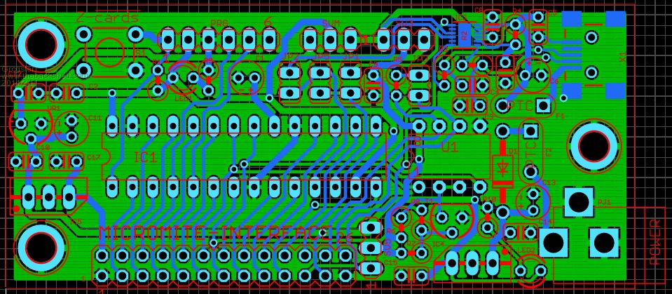
Sprint Layout uses different colours to that of Eagle etc, so this is why it is a different colour. Sprint Layout 6 thinks that the top copper layer is blue, and the bottom copper layer is green. Top silkscreen is red, and no bottom silkscreen. Smoke makes things work. When the smoke gets out, it stops! |
||||
| bigmik Guru Joined: 20/06/2011 Location: AustraliaPosts: 2981 |
My God, I nearly gagged on my coffee... $14 US each for 25 teeny weeny PCBs seems way out of kilter with what I believe is readilly available... If it is YOUR price for a one off then OK I understand as you have to make it worth your while but at that price it doesnt give you any margin.. I would have guessed that 50 boards would set you back around $100-$120 US. inc postage. I have used OURPCB.COM ... somewhere on their site (horrible to navigate) is an estimate but best to get a quote first.. The best price I have found is a company called sales@sitopway.com In both the above companies I have found the quality to be excellent.. Regards, Mick EDIT **** I just used OURPCB.COM calculator for a 3.5cm x 8cm PCB 2 sided Online calculator And QTY 50 came out as $115 US and 100 was $150 US.. but it is only a rough guide and varies depending on the panel sizes so quotes are best. One thing I liked about Sitopway.com was the EMS courier was only about $15 where as many others want upto ten times that. Regards, Mick Mick's uMite Stuff can be found >>> HERE (Kindly hosted by Dontronics) <<< |
||||
| Zonker Guru Joined: 18/08/2012 Location: United StatesPosts: 772 |
Thanks Gent's for info on pricing of the PCB's... I was just going through the process to see what kind of price I would get back... (sorry bout the coffee Mick)..
Thanks TZ and Mick for the PCB suggestions.. I came home from work and did a clean-up pass on the project, changing a few things... I re-spun the files and updated the doc files and added a BOM. Since I was looking over the ITEAD Studio site, I stored the artwork files in their file type names. I put a legend in the BOM for the layer names Hopefully, this should be a good release of the project. Thanks in advance for any feedback..!!
Zonk 2014-02-12_024141_MicroMite_Prototype_Board_All_Files.zip |
||||
| Grogster Admin Group Joined: 31/12/2012 Location: New ZealandPosts: 9975 |
You really should check out Futurlec - they have an American site, among others all over the world, but they have a PCB service which is very well priced. Futurlec USA I put in your board dimensions, double-sided, silkscreen and soldermask, and they are $2.25 a board(in American dollars) + setup and freight, but that is a one-off cost no matter how many boards you get. I have used Futurlec for years, and although the 1-week turnaround is a bit optimistic(it's usually about three weeks I have found), the boards themselves are very good quality, and I have always been happy with their product. Smoke makes things work. When the smoke gets out, it stops! |
||||
| The Back Shed's forum code is written, and hosted, in Australia. | © JAQ Software 2026 |
