
|
|
Forum Index : Microcontroller and PC projects : MicroMite Elevator...
| Author | Message | ||||
bigmik Guru Joined: 20/06/2011 Location: AustraliaPosts: 2981 |
Yes, That. Is it.. I reckon it would work. Mick Mick's uMite Stuff can be found >>> HERE (Kindly hosted by Dontronics) <<< |
||||
Grogster Admin Group Joined: 31/12/2012 Location: New ZealandPosts: 9974 |
Sweet - will try it....  ...tomorrow. ...tomorrow.
Nighty night, everyone. Smoke makes things work. When the smoke gets out, it stops! |
||||
| bigmik Guru Joined: 20/06/2011 Location: AustraliaPosts: 2981 |
Groggy, Of course that will only work on a 3.3v power source.. 5v would light both leds. Mick Mick's uMite Stuff can be found >>> HERE (Kindly hosted by Dontronics) <<< |
||||
CircuitGizmos Guru Joined: 08/09/2011 Location: United StatesPosts: 1427 |
You could use I2C or you could use SPI. I've noticed SPI seems easier for people to understand and implement. If you have a Micromite for all of your outputs and another for your inputs then the third Micromite could actually be a Maximite while you develop things. Micromites and Maximites! - Beginning Maximite |
||||
| Grogster Admin Group Joined: 31/12/2012 Location: New ZealandPosts: 9974 |
Hi folks. 
@ Mick: Re - 3v3 - yes, acknowledged and I agree. I have at this stage settled on basing the project on two uM chips for the moment. Both 44's. One uM is the input processor, and the other is the output processor, and both talk to each other about what is going on using I2C or SPI. The 44's have 33 IO pins, and we lose two to the I2C link, leaving 31 IO pins per chip, which gives me plenty of IO pins to play with. @ CG - Don't let MOBI hear you suggest that I2C is difficult!!! 
I need to play with I2C, so this project will help with that, so at this time anyway, I am planning to use I2C. I also need to study I2C a bit more in terms of if you can setup interrupts with it like you can with serial ports or standard pins - I might need some handshaking pins between the chips(as interrupts) to tell the other chip that they want to talk on the I2C bus. ...there is A-LOT to think about, even for a model elevator - much more then I first thought... Still, a great way for me to spend my nights, rather then sucking back the beer, and this project is exactly what I NEED - a distraction, you see.  Smoke makes things work. When the smoke gets out, it stops! |
||||
donmck Guru Joined: 09/06/2011 Location: AustraliaPosts: 1314 |
Let's see. 5 of Mick's simplistic version home brew Micromites would be less than $50. String them together with I2C. I won't even do the maths on it, as I know it should be well more than the project needs. Cheaper than using additional circuitry to cater for I2C expansion, and other conversions. Cheers Don... https://www.dontronics.com |
||||
| bigmik Guru Joined: 20/06/2011 Location: AustraliaPosts: 2981 |
Hi Grogster, |
||||
| Grogster Admin Group Joined: 31/12/2012 Location: New ZealandPosts: 9974 |
That's nice to know - I have not cleared the bench yet in order to try it out! 330R is normally a good value at 3v3, so I will try that value too, and see what happens. This is more academic then anything else at this point, as since I decided to use two 44's, I have plenty of pins, and can drive the UP and DN arrow LED strings with seperate output pins and suitable buffer transistor driver. In fact, I have added another floor to the design, as there are enough pins now. So six storey, or five story and ground, depending on how you want to look at it. I have lots of exciting bits coming - eBay and a VISA card can be dangerous like that!  But most of those bits are so flippin' cheap on eBay - I think I spent about $50 in total, and got the pulley wheels for the "Sheave" 40 photo-interrupters(won't need all of them), 4 metal-gear reduction drive motors, 4 servos, and I even grabbed a couple of stepper-motor driver kits(with 4-phase motors). But most of those bits are so flippin' cheap on eBay - I think I spent about $50 in total, and got the pulley wheels for the "Sheave" 40 photo-interrupters(won't need all of them), 4 metal-gear reduction drive motors, 4 servos, and I even grabbed a couple of stepper-motor driver kits(with 4-phase motors).
While I wait for that stuff to arrive, this will give me time to work on building the "Shaft" and cabin. My design at this stage, will be reasonably open, so that you can see inside, and see what it is doing etc. Smoke makes things work. When the smoke gets out, it stops! |
||||
| Grogster Admin Group Joined: 31/12/2012 Location: New ZealandPosts: 9974 |
An update for this thread. I have 50 or so photo-interrupter PCB's all ready to go for the shaft sensors. Today I built the "Core" of the "Building".
The building will be 6 floors with ground and basement, so 8 levels in total. Unlike a "Proper" core, my building won't have anything other then the shaft guide-rails, so you can see what is going on when things start moving etc. At real-life structural level, the guide-rails will support the fake core of the building, and I will add MDF strip corners to the building which run right up the side, to hold the outside edges together. I am using those rails you buy for adjustable shelving, turned around the other way to act as guide rails for the cabin and counterweight. The cabin has four guide rails, and the counterweight has two. The rails are 1500mm long each, with holes for screws every 200mm, so my "Floor spacing" is 200mm centres, just cos it is nice and easy to adopt what is already factory punched for you. I have cut the eight floor slabs from 18mm MDF, using a local joiner business to cut the 200mm centre holes which will become the actual shaft. I got the joiner to do this, cos they are neater then my hand and a jigsaw, and to prevent warping the guide-rails and causing things to stick, the shaft holes in the floor slabs need to be as accurate as possible - much difference between floors would bend the guide-rails, and cause the cabin to stick rather then ride up and down nicely. We're into daylight saving now, so I hope to be able to spend an hour or so on construction after work from now on. I will post photos in the next day or so. Smoke makes things work. When the smoke gets out, it stops! |
||||
| Grogster Admin Group Joined: 31/12/2012 Location: New ZealandPosts: 9974 |
I forgot to post the photo ages ago: 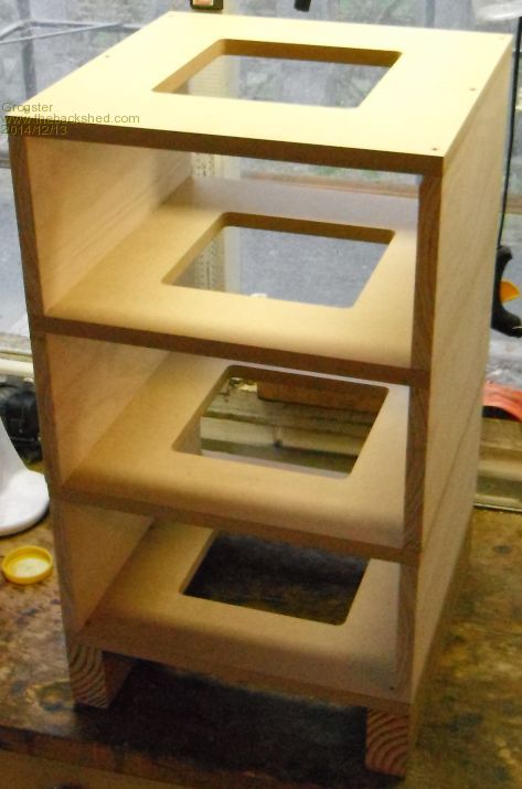
This shows the first four floors out of eight in total, so this is the building under construction at 50% of it's final design height, but you can easily see the elevator "Shaft" and how the floors will look. I changed the design a little and decided to put left and right walls in for structural reasons. I was just going to put little corner bits in, but it was easier and involved less cutting to just make "Walls". The front and back will remain completely open, so you can see the cabin and counter-weight riding up and down on the guide-rails. I plan to put the remaining floors on it tomorrow so that I can then paint it to protect the wood. Once I have done that, I will set about installing the guide-rails, cabin, counter-weight, cables, sheave and motor. Still plenty to do, but it should be a somewhat unique project among my others! Smoke makes things work. When the smoke gets out, it stops! |
||||
| WhiteWizzard Guru Joined: 05/04/2013 Location: United KingdomPosts: 2985 |
Grogs, Did you ever complete this project?? I see it was a year ago you last posted and was wondering if it ever got finished. The reason for asking is that my 3yr son is MAD about lifts (we can't go past a shop without going in the lift first!). I have just built him one in Lego but it ain't that great. If you made progress, could you post a video so I can show him!! Would love to build one with him too (with the latest 100pin MM of course!!) Thanks, WW |
||||
| Grogster Admin Group Joined: 31/12/2012 Location: New ZealandPosts: 9974 |
Bloody hell! Time flies...... 
I have not finished it - it is in a state of limbo, currently sitting as an empty 6 floors + basement shell. 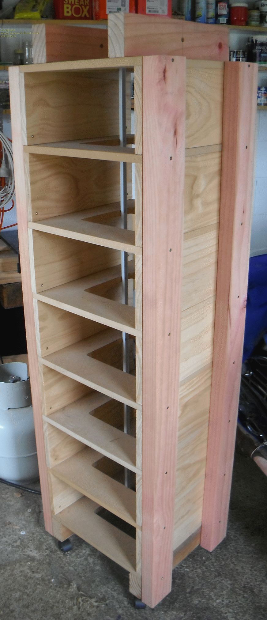
The original plan I think, was to use three MM 150's and connect them using I2C - will have to re-read this thread. Now, as you say, it would be via a 100-pin MM+ and graphical display. Hopefully, over the Christmas break, I might be able to do some more on it. If your son is lift mad, have a look on YouTube lots of videos there, and mrmattandmrchay has some good elevator videos. The project is not dead though, but needs a little rethinking....... Smoke makes things work. When the smoke gets out, it stops! |
||||
| Grogster Admin Group Joined: 31/12/2012 Location: New ZealandPosts: 9974 |
UPDATE: I have not abandoned this project, but there never seems to be any time to play with it at the moment! Having said that, I did play with a concept on the sensor input, which will DRASTICALLY cut back on all the I/O pins needed for the sensors. Conceptually, I plan to use a multi-turn pot similar to these which can be had very cheaply on eBay these days. Number of floors divided by 10 to work out how much of a turn you need on the multi-turn pot per 'Floor' - this involves custom making a wooden pully for the pot, that will turn the pot the correct amount depending on the number of floors you need to cover. The easiest way to do this is probably TWO wooden pullys, with one on the pot at the top of the shaft, and the other one in the basement at the bottom of the shaft, linked with a loop of 'Rope'. The rope is secured to the cabin itself, so that when it moves, this will result in the rope moving both pullys, and therefore, the position of the pot. All that would be quite easy to build, as it is simple and only needs two suitably sized wooden pullys to be made. The idea being that at basement level, the pot will read zero, and at the top floor, the pot will read 10k. With that in mind, you can then use the pot and ONE single analog input pin, to read the pot, and thus the one pot will do ALL the shaft sensor work. Just by reading the analog input pin, the MM will know exactly where in the shaft the cabin is, and once you manually set the floor-level readings from the pot(only needs to be done once), the MM will then have reference points for all the floors, so will know exactly when to stop the cabin, and it will be level with the floor. What this means, is that the entire project could probably be controlled with ONE 170 MM2 chip - and still have enough pins to have an SPI touch-screen for control. In reality, I plan to use a 44-pin MM2 chip. This is a low-priority project, however, the saga for this one continues..... Smoke makes things work. When the smoke gets out, it stops! |
||||
palcal Guru Joined: 12/10/2011 Location: AustraliaPosts: 2039 |
This will take the Micromite to a new level  . .The pulleys on the pot? seems like too much room for error and not technical enough. What about a stepper motor on the pot. Paul. "It is better to be ignorant and ask a stupid question than to be plain Stupid and not ask at all" |
||||
| Grogster Admin Group Joined: 31/12/2012 Location: New ZealandPosts: 9974 |
There is a stepper motor as the main sheave motor at the moment. Why would you put a stepper motor on the pot? The idea is to have the cabin movement, alter the position of the pot. The cabin has to be physically connected to the pot, so that the pot position is relative to the cabin position - a stepper motor would not do that. Can you clarify? ...or are you pulling my leg... Smoke makes things work. When the smoke gets out, it stops! |
||||
| palcal Guru Joined: 12/10/2011 Location: AustraliaPosts: 2039 |
Probably didn't think it through, but I assumed the cabin would move at a steady speed and the pot could be controlled by advancing it a certain number of steps for each level. Paul. "It is better to be ignorant and ask a stupid question than to be plain Stupid and not ask at all" |
||||
| MicroBlocks Guru Joined: 12/05/2012 Location: ThailandPosts: 2209 |
I would also add a switch on each level. These could be connected to a single pin by connecting each switch in parallel. The pot will give you the voltage to and the switch will tell you the exact spot to stop. Little variances in voltage will then not matter and you could actually use the switch to determine the exact moment the value from the pot is at each level. Microblocks. Build with logic. |
||||
| Paul_L Guru Joined: 03/03/2016 Location: United StatesPosts: 769 |
Since the motor than drives the cabin up and down is a stepper you could just count the number of pulses you need to move the cabin from floor to floor and just deliver that many pulses to the motor. You could calibrate it by stepping it up or down in small increments until it was level at one floor. Paul in NY |
||||
| Grogster Admin Group Joined: 31/12/2012 Location: New ZealandPosts: 9974 |
Another couple of good ideas. I will take them under advisement. Smoke makes things work. When the smoke gets out, it stops! |
||||
| CaptainBoing Guru Joined: 07/09/2016 Location: United KingdomPosts: 2171 |
This is a nice thread. It is the process of mundane things like elevators that has always fascinated me, the things you don't notice but actually have a burden of unappreciated thought that has gone into them. As a callow youth, I worked for a small electronics company that specialised in small-run bespoke projects and we subbed to a lift manufacturer to produce a microprocessor controlled unit (1984) using Z80s. We provided lots of little trinkets; two I especially liked was "invitation to board" which during slack periods, always positioned one elevator at the ground floor with the doors open and scattering idle cars across the floors to minimise delay when calling - that went down really well but I don't see it often. Second was the balancing algorithm for the tidal flows of the work day... we went to all sorts of trouble with clocks and stuff then we realised that it was really easy to implement (and self-adjusting) that if a car is idle and is called to a floor, return it to that same floor when it becomes idle again. This way if all the cars are needed at the ground at the start of the day, people get in and go up, then instead of sitting there, it returns to the ground. At the end of the day the same thing happens, people from the floors call idle cars to, say the 4th, then when it becomes idle it returns to the 4th where there is evidently a flow. happy days. The building i am in at the moment has a really stupid controller. cars will just sit at the last floor they visited and if two or more at at the same floor, there is a huge delay while it works out which car to offer. Very often I see 2 or 3 cars at the top floors doing nothing and then there is a huge wait while the thing decides which it is going to send down. The number of times I have wished I could get "in there" and tweak it - such a geek |
||||
| The Back Shed's forum code is written, and hosted, in Australia. | © JAQ Software 2026 |
