
|
|
Forum Index : Microcontroller and PC projects : MicroMite resetting
| Author | Message | ||||
OA47 Guru Joined: 11/04/2012 Location: AustraliaPosts: 1050 |
Jim I have tried the code with the error routine remmed out. BTW I did set a count to print how many times it looped in the sub before the crash. Over 20 runs it crashed anywhere between 0 and 386 loops. It did get right through at least once in my testing. Just to mention I originally wrote this code for the Maximite and it worked flawlessly as I mentioned on an earlier post (getting the mites to talk over VF UHF radio) Thanks for your input |
||||
TassyJim Guru Joined: 07/08/2011 Location: AustraliaPosts: 6541 |
I still would like to be sure that you are not calling the sub a second time before it has finished. To measure the time taken for this sort of code, I set a spare pin high at the start and low at the end. The CRO will then give a very accurate indication of the time taken and the time between calls. When I have finished with the CRO, I usually put a LED on to act as an activity indicator. Analog in is relatively slow and you are taking a lot of readings. It would be interesting to measure the difference in time between the micromite and maximite for a full set. Jim VK7JH MMedit |
||||
| OA47 Guru Joined: 11/04/2012 Location: AustraliaPosts: 1050 |
Jim, I am currently activating an LED on pin(7) to indicate the presence of the CD signal. Currently in the test setup the maxiite is sending one word (11 bits) each 30 seconds and I can see the signal at the micromite pin(25) with the CRO. The reset happens at the start of the signal or somewhere during and of course the LED shuts off because of the reset. The CD is operated about 1000ms before the signal to allow the radio to come out of sleep mode and the signal(11 bits @50ms)is around half a second. As I am not using the interrupt to call the sub I dont think that it could be called more than once without ending. I have been counting around 500 samples on the micromite when the sub does work. Thankyou again for your input |
||||
| TassyJim Guru Joined: 07/08/2011 Location: AustraliaPosts: 6541 |
I should have thought about it sooner but are you running the radios physically close to the micromite. It could be RF getting in. Preferably, the transmitting radio should be well away from the receiving micromite and using a dummy load for the antenna. A few 0.1uF or 0.01uF capacitors and ferrite filters on the power rails are a good idea. Also, can you do the testing without the radios. Just audio to audio for now. Jim VK7JH MMedit |
||||
| OA47 Guru Joined: 11/04/2012 Location: AustraliaPosts: 1050 |
Jim, good thoughts, the UHF radios are completely di-cast boxed with a remote antenna and the PCB with the micromite does piggy back to these boxes. I did not have this problem when trying just measuring frequency with the same hardware setup and I am not transmitting from the unit while testing monitoring the current usage does not exceed 100mA so that would confirm that. |
||||
| TassyJim Guru Joined: 07/08/2011 Location: AustraliaPosts: 6541 |
Next test. Remove the audio from pin 25 and put a fixed voltage on it. Jim VK7JH MMedit |
||||
| OA47 Guru Joined: 11/04/2012 Location: AustraliaPosts: 1050 |
Attached AAA battery to pin 25. At prompt Print pin(25). Result 1.373. From Maximite pin(9)=0:pause 500:pin(9)=1 'simulate 500ms of PTT Result micromite reset Just to add to the confusion, I have a momentary switch on pin(15) via a 1K resistor to ground. I have added a routine to print the counts and resultant voltage read on pin(25) this I have been loading into a .CSV file and presenting it to excel so I can see the shape of the data word.(I was able to graphically show this on the Maximite) With the AAA connected and button pressed I got 836 readings of 1.36 volts and no crash. |
||||
| TassyJim Guru Joined: 07/08/2011 Location: AustraliaPosts: 6541 |
Is the Maximite pin 9 connect directly to pin 15 on the micromite? Do you have the 0V lines connected also? I am thinking about earth loops or 'floating' voltages.... Jim VK7JH MMedit |
||||
Grogster Admin Group Joined: 31/12/2012 Location: New ZealandPosts: 9979 |
What would be the chances of you uploading a photo of how things are connected up? That, or a schematic diagram - just freehand pen and paper would do... This thread is intensely interesting to me, although I have no bright ideas to contribute at this point.... Smoke makes things work. When the smoke gets out, it stops! |
||||
| OA47 Guru Joined: 11/04/2012 Location: AustraliaPosts: 1050 |
|
||||
| OA47 Guru Joined: 11/04/2012 Location: AustraliaPosts: 1050 |
@Grogster: 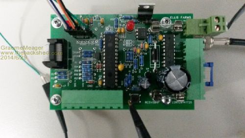
The schematic is close to being accurate, I have made a few modifications over the past few days. 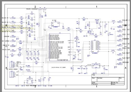
|
||||
| Grogster Admin Group Joined: 31/12/2012 Location: New ZealandPosts: 9979 |
Thanks, Graeme. 
Could you please put the photo and the schematic into a ZIP and post that? Not your fault - forums have re-sized the schematic so much so, it is unintelligible. 
EDIT: Your PCB looks fantastic, I must say.... Smoke makes things work. When the smoke gets out, it stops! |
||||
| OA47 Guru Joined: 11/04/2012 Location: AustraliaPosts: 1050 |
@Grogster I'll try again: 2014-06-29_092718_RCS_REMOTE_SCHEMATIC.zip 2014-06-29_092923_pcb_2.zip PS Grogster this project is a love job I have taken on for my brother-in-law on his farm. An upgrade to a system I installed many years ago, it is times like this I wish I hadn't said yes.  |
||||
| Grogster Admin Group Joined: 31/12/2012 Location: New ZealandPosts: 9979 |
Yes, very nice PCB indeed. At first glance(and I have not had an in-depth look at it yet), I don't see anything obviously wrong electronically, based on your schematic. I will keep a close eye on this thread, and see what others come up with. As to the wishing you had never said yes, well - most of us here have ALL had that at some point, but it really is time for drinkies(alcoholic or not, depending on your stance) once you finally crack what the problem is, so do hang in there, as we all do want to find out what the issue is - if that is not being to presumptuous of me with respect to the other members of the forum!!! I am GUESSING that you tested this out on a breadboard BEFORE you got the PCB done, so can therefore be reasonably sure that it should have worked? EDIT: Looking at the schematic - do you really need 1000uF on the 3v3 rail? Seems like rather a-lot to me... If the radio works on 3v3, then the cap should be on the radio-side of the PSU, not on the MCU side of the PUS. My 2c only.... Also, 4700uF on the input to the regulator? OK if the MCU was to be sucking a couple of amps, but it won't be. Smoke makes things work. When the smoke gets out, it stops! |
||||
| OA47 Guru Joined: 11/04/2012 Location: AustraliaPosts: 1050 |
To be honest Grogster I originally tested the low speed data transmit and receive on a Maximite thinking the process would be the same on the micromite. (Error #1 Major Assumption) I set up the micromite system using a pin with FIN function and in an effort to speed up the process I ordered some prototype PCBs only to find later that the micromite cannot give an accurate frequency measurement without a large sample. This meant that I had to re-think and rectify the incoming signal and use the AIN pin to differentiate between logic low and high. Now this has brought up this problem of re-boots. BTW I did fire up one of the original boards using FIN on pin 15 instead of AIN on pin 25 and the software does not re-boot. |
||||
| vasi Guru Joined: 23/03/2007 Location: RomaniaPosts: 1697 |
The board is very nice. Maybe is time to rewrite the application in Firewing BASIC? Hobbit name: Togo Toadfoot of Frogmorton Elvish name: Mablung Miriel Beyound Arduino Lang |
||||
| TassyJim Guru Joined: 07/08/2011 Location: AustraliaPosts: 6541 |
More guessing. Could you try removing R13 (the 1k resistor in the speaker line) or short out D11. This effectively removes the audio without changing anything else. If the micromite no longer resets, I expect that you are overloading the analogue inputs. The 1N746A has a fairly large forward voltage drop (but I couldn't find a low current figure) and that might be upsetting things when the input goes negative. A resistor after the diode, between the diode and pin 25 should be enough to fix that problem. Without a resistor, the diode is in parallel with the internal protection and the internal is probably doing all the work. A Schottky diode in parallel with the zener might also work. You appear to have good protection in your circuit and there looks like a 0.1uF cap close to the analogue supply pins. The analogue ground is important and a re-arrangement of the ground traces might be needed. This is getting into an area which seems like black magic and not my best area. I usually put in lots of isolation transformers and relays or opto-isolators for the PTT. I am finding the exercise interesting and as I have a couple of RF interface projects in the to-do pile, a solution to the problem will be great! Jim VK7JH MMedit |
||||
| OA47 Guru Joined: 11/04/2012 Location: AustraliaPosts: 1050 |
Have done a lot more experimentation and I am convinced that there is a spike at the start of the audio train that I cant pick up on the CRO but this is going over the limits of the analog input which is resetting the Micromite. The 5V tolerant inputs can cope with it ok. I have attenuated the signal by 75% and the software is stable but know I have to put up with RC components that are making the task of identifying the highs and lows difficult. I will have to play around with the component values to achieve the attenuation and try to keep the squareness of the resultant waveform. Thank you for everyone's contributions I am sure that I will again need the forums help before this project is finished. GM |
||||
| Grogster Admin Group Joined: 31/12/2012 Location: New ZealandPosts: 9979 |
Congratulations - you are making progress then, and it would seem, are homing in on the source of the problem. Looks like Jim was right!  Smoke makes things work. When the smoke gets out, it stops! |
||||
| aargee Senior Member Joined: 21/08/2008 Location: AustraliaPosts: 255 |
If you suspect too much voltage on the audio line, try putting two 1N4148 diodes back to back (one A to signal, K to earth and the other K to signal and A to earth) across the line to earth. This effectively limits the voltage to 0.7V, any AC above that and the diode will conduct. For crying out loud, all I wanted to do was flash this blasted LED. |
||||
| The Back Shed's forum code is written, and hosted, in Australia. | © JAQ Software 2026 |
