
|
|
Forum Index : Microcontroller and PC projects : 8, 14 & 18 pin DIL versions of 170 uM...
| Author | Message | ||||
Grogster Admin Group Joined: 31/12/2012 Location: New ZealandPosts: 9975 |
Looking at the datasheet, page 305, there IS a metal pad on the bottom of these chips. Does it really matter if it is not connected to ground? There are three other ground pins on the chip itself..... Here is what I have so far: 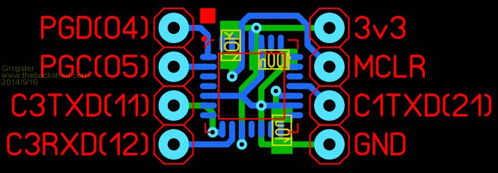
This is still 1.5x DIL footprint(10mm). The numbers in brackets represent the pin numbers from the standard 28-pin DIL package that I have used. Smoke makes things work. When the smoke gets out, it stops! |
||||
bigmik Guru Joined: 20/06/2011 Location: AustraliaPosts: 2981 |
Grogs, I just got home and started downloading the data sheet now. The pad itself `may' be connected to GND, if so it is a risk if we were to run tracks under the chip on the top layer.. I am about to look at layout options, but I dont wish to step on your feet, I am just curious about what we can come up with. Mick Mick's uMite Stuff can be found >>> HERE (Kindly hosted by Dontronics) <<< |
||||
| Grogster Admin Group Joined: 31/12/2012 Location: New ZealandPosts: 9975 |
By all means - step away! 
How small can vias be? There must be a minimum, especially the hole size.... I may well be able to scrape some space back, IF the vias can be smaller. Perhaps we need to go to 4-layer?  Smoke makes things work. When the smoke gets out, it stops! |
||||
| Grogster Admin Group Joined: 31/12/2012 Location: New ZealandPosts: 9975 |
Here is my latest effort - all vias removed from under the chip where the pad is. 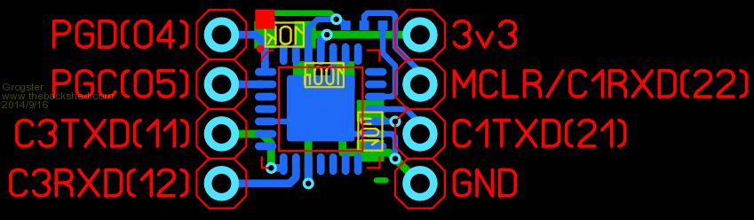
This layout also allow re-use of MCLR pin - it becomes the COM1 RXD when you solder-blob across the pads at the top of the module. You just need to move the solder-blob, if you ever need to update the firmware. Smoke makes things work. When the smoke gets out, it stops! |
||||
| Grogster Admin Group Joined: 31/12/2012 Location: New ZealandPosts: 9975 |
@ Mick - Page 5 of manual, very bottom: I am therefore using this plane, as a ground connection for the ground requirements of the chip itself. Smoke makes things work. When the smoke gets out, it stops! |
||||
| Grogster Admin Group Joined: 31/12/2012 Location: New ZealandPosts: 9975 |
Another update. 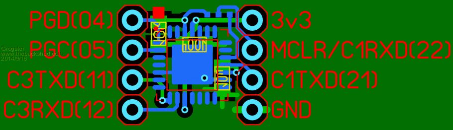
Now with ground-plane on copper2, linked to the ground-plane on copper1, which is then connected to all the chip ground points. Moved 10k pull-up resistor. Smoke makes things work. When the smoke gets out, it stops! |
||||
| bigmik Guru Joined: 20/06/2011 Location: AustraliaPosts: 2981 |
Grog, Have you looked at the SSOP chip? It will probably be easier to solder and you can run tracks under the chip? I am playing with that one now. Mick Mick's uMite Stuff can be found >>> HERE (Kindly hosted by Dontronics) <<< |
||||
| Grogster Admin Group Joined: 31/12/2012 Location: New ZealandPosts: 9975 |
Yes, I did look at that one, but the SSOP is longer then the 8-pin footprint. True, you can get tracks under it, but it is too "Big" 
I suppose it is only JUST longer, and the SLIGHTLY larger PCB size would not really matter that much, eh? I've ordered the QFN's already(a couple of days ago), so I might as well see what I can come up with. I would expect that QFN's are NOT hand-solderable due to their size and footprint, but hot-air or an oven should do it. It's a chance for me to play with the QFN package, in any event. Smoke makes things work. When the smoke gets out, it stops! |
||||
| bigmik Guru Joined: 20/06/2011 Location: AustraliaPosts: 2981 |
Grogs, I have reverted to the SSOP for several reasons, 1. Solderability 2. Tracks underneath the chip on top layer are OK 3. it is only 10mm x 7mm in size.. (by my understanding of the specs) not big at all Mick Mick's uMite Stuff can be found >>> HERE (Kindly hosted by Dontronics) <<< |
||||
| Grogster Admin Group Joined: 31/12/2012 Location: New ZealandPosts: 9975 |
Yep, all fair points. The 10x7 size is pretty much exactly the same size as an 8-pin DIL - no room at all for any tracks anywhere. By all means, design something and pop it up here for ME to look at this time! Smoke makes things work. When the smoke gets out, it stops! |
||||
| viscomjim Guru Joined: 08/01/2014 Location: United StatesPosts: 925 |
Grogster, since you already are getting the qfn packages, you should probably get your uMite controlled reflow oven working for your production runs. |
||||
| Grogster Admin Group Joined: 31/12/2012 Location: New ZealandPosts: 9975 |
Well, that is one of the reasons I thought I would build the oven, and bought the QFN's. If it is a dismal failure, the chips are cheap enough that it would not break the bank. But I don't see failure as being possible - think positive! Smoke makes things work. When the smoke gets out, it stops! |
||||
| WhiteWizzard Guru Joined: 05/04/2013 Location: United KingdomPosts: 2991 |
@Grogs - worst case scenario is you end up with some 'fried chips' from your oven!!
|
||||
| Grogster Admin Group Joined: 31/12/2012 Location: New ZealandPosts: 9975 |
HAHAHA!!!!  Smoke makes things work. When the smoke gets out, it stops! |
||||
| vegipete Guru Joined: 29/01/2013 Location: CanadaPosts: 1179 |
I've looked at putting physically tiny chips onto DIP like PCB's in the past too. It becomes clear that standard DIP sizes have real practical benefits. 40 pin .600 wide ones are easy. But this 8 pin DIP concept is interesting. An idea I had in the past was to use 'semi-depinned fine pitch headers' (if I may create some silly techno-babble.) I've attached an image of a quick 8 pin DIP layout. The trick is to use something like a 7 pin .050" header for each side. With pins 2,4 and 6 pulled out, it becomes the correct 4 pin header. The pins are a smaller size than the .025 square pins on standard headers which suits plugging into sockets better. The other detail is the 4 center pins. As mentioned before, surface mount pins won't be overly robust. So I suggest that the 4 corner pins can be through hole, the 4 inner pins can be bent over and soldered surface mount style. As drawn, the 4 blue pads are for pins bent inwards, but outwards could work too if needed. As much as possible, the 8 pin PCB should match the pinouts of, say, a PIC12F675. I'm not sure that the main pins need to include the ICSP/Debug pins - I've roughly drawn them connecting to a typical header, except with 1mm pitch (although PGD & PGC are likely reversed.) This would allow the device to be debugged in-circuit without consuming limited pins. An side benefit is that the USB D+/- pins of an 'MX2xx are automatically available on that same header for a possible USB port. Food for thought... Of course, if you are reflowing anyways, those 36 pin VTLAs are even smaller. 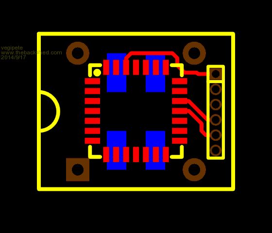
Visit Vegipete's *Mite Library for cool programs. |
||||
| Grogster Admin Group Joined: 31/12/2012 Location: New ZealandPosts: 9975 |
Yeah, the VTLA's are the smallest package you can get these PIC32's in, I think. Perhaps next time....
Currently, I have two versions I am getting prototyped, cos I already have a PCB waiting to get made, but was going to be bigger then 50x50, so have to use the 100x50 iTead service, so I might as well add these little boards to the panel, so I get some of them to play with at the same time. 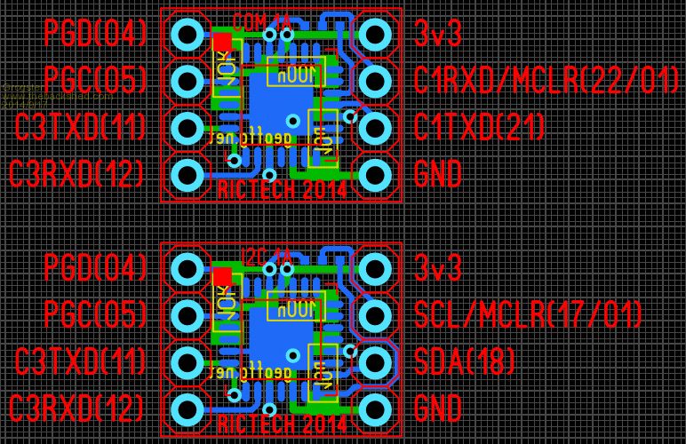
The one labelled "COM 1A" is for serial port use, and "I2C 1A" is for I2C use. I am one pin short on the 8-pin idea, to be able to make an SPI one, due to the extra SPI line. Both these boards are 13mm x 10mm(1.5x DIL) in size. Smoke makes things work. When the smoke gets out, it stops! |
||||
| viscomjim Guru Joined: 08/01/2014 Location: United StatesPosts: 925 |
Why don't you make a 28 pin dil version of that with the qfn package on it. That way you can bring out all 28 pins.... I couldn't resist... |
||||
| bigmik Guru Joined: 20/06/2011 Location: AustraliaPosts: 2981 |
Hi Jim, If you multiplex power and GND you can save a pin 
Mick Mick's uMite Stuff can be found >>> HERE (Kindly hosted by Dontronics) <<< |
||||
| viscomjim Guru Joined: 08/01/2014 Location: United StatesPosts: 925 |
Hi Mick, If you add 2 8 port I2C chips, you can make a 44 pinner!!!! |
||||
| MicroBlocks Guru Joined: 12/05/2012 Location: ThailandPosts: 2209 |
The 170 does not come in a 36 pin VTLA package so the QFN is still the smallest. I am not sure about the need for an 8 pin version that does not fit an 8 pin DIP socket. Seems to defeat the purpose. If fitting a DIP-8 is not a requirement then it becomes a exercise to fit as much as possible in as little space as possible. A fun thing to do anyway. I would then not connect the PGD/PGC and Console RX/TX to pins but use it for other functionalities such as SPI or I2C or IR etc.. If you have the PGD/PGC available as a header of even just as a solder island you can still program it. You would then build you program and test it on a full size version, save the program. Read the complete content of the flash, and program that into the 8 pinner. My 8 pinner would have: VDD, VSS, I2C, Com1 +EN for serial and rs485 and IR. Microblocks. Build with logic. |
||||
| The Back Shed's forum code is written, and hosted, in Australia. | © JAQ Software 2026 |
